2500_Users_Manual-.pdf - 第199页
1 TEMPORARY FILE SELECT POSITION OF PIN 1 TXT IN REL ATION TO THE TEXT. USE AR ROW KEYS THEN PRESS ENTER. <----- -- TEMPORARY FILE SELECT POSITION OF PIN 1 AS IT WILL GO INTO THE TUBE. 1 USE AR ROW KEYS THEN PRESS ENT…
PROGRAM/TEST LABEL TEMPORARY FILE
ENTER PART LENGTH: _
EXAMPLE: 1.234 OR .28 OR 1
PROGRAM/TEST LABEL TEMPORARY FILE
ENTER PART LENGTH: _
LENGTH CAN NOT EXCEED 2.250
PRINT LABEL TEMPORARY FILE
AUTO-SEL 26 CPI 26 CPI S 20 CPI
18 CPI 16 CPI T 12 CPI T
MOVE TO SELECTION THEN PRESS ENTER
1 <------- TEMPORARY FILE
SELECT POSITION OF PIN 1
AS IT COMES OUT OF THE TUBE.
USE ARROW KEYS THEN PRESS ENTER.
Preventive
Maintenance
Type
Size
Device
Orientation
in
Input
Tube
To
select
a
custom
device
for
which
you
determine
the
length,
move
the
cursor
to
CUSTOM,
and
press
ENTER.
The
2500
displays:
Type
the
length
of
your
device
in
inches,
up
to
three
decimal
places
and
under
2.250
inches.
Press
ENTER.
If
you
type
an
invalid
number,
the
2500
displays:
Type
a
valid
number
and
press
ENTER.
After
you
have
selected
an
existing
device
or
entered
a
valid
length
for
your
custom
device,
the
2500
displays:
“S”
indicates
a
short
font,
which
allows
more
lines
to
be
printed
on
the
labels.
Select
the
font
you
want
and
press
ENTER.
The
2500
displays:
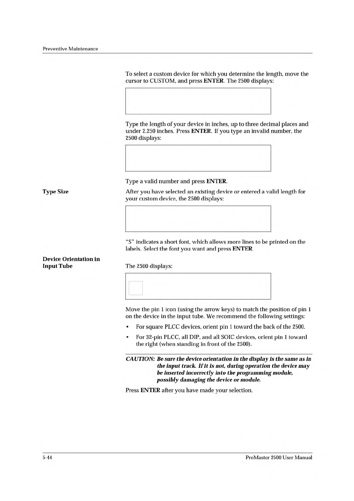
Move
the
pin
1
icon
(using
the
arrow
keys)
to
match
the
position
of
pin
1
on
the
device
in
the
input
tube.
We
recommend
the
following
settings:
•
For
square
PLCC
devices,
orient
pin
1
toward
the
back
of
the
2500.
•
For
32-pin
PLCC,
all
DIP,
and
all
SOIC
devices,
orient
pin
1
toward
the
right
(when
standing
in
front
of
the
2500).
CAUTION:
Be
sure
the
device
orientation
in
the
display
is
the
same
as
in
the
input
track.
If
it
is
not,
during
operation
the
device
may
be
inserted
incorrectly
into
the
programming
module,
possibly
damaging
the
device
or
module.
Press
ENTER
after
you
have
made
your
selection.
5-44
ProMaster
2500
User
Manual
1 TEMPORARY FILE
SELECT POSITION OF PIN 1
TXT IN RELATION TO THE TEXT.
USE ARROW KEYS THEN PRESS ENTER.
<------- TEMPORARY FILE
SELECT POSITION OF PIN 1
AS IT WILL GO INTO THE TUBE.
1 USE ARROW KEYS THEN PRESS ENTER.
_ | TEMPORARY FILE
| COLUMN X ROW X
| PRESS STOP WHEN
| EDITING IS COMPLETE.
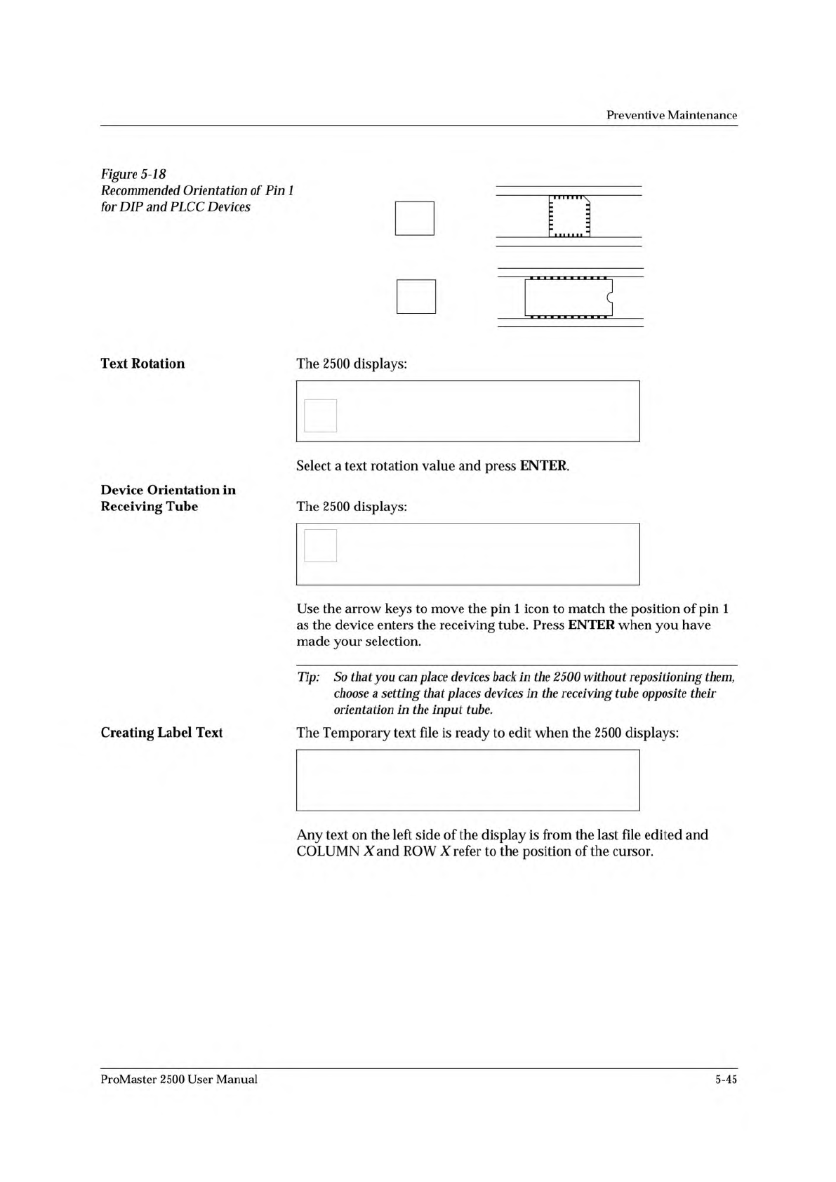
1
SQUARE
PLCC
1
DIP, SOIC
32-PIN PLCC
FRONT PANEL DISPLAY
IN INPUT TUBE
1256-2
Preventive
Maintenance
Figure
5-18
Recommended
Orientation
of
Pin
1
for
DIP
and
PLCC
Devices
Text
Rotation
Device
Orientation
in
Receiving
Tube
Creating
Label
Text
The
2500
displays:
Select
a
text
rotation
value
and
press
ENTER.
The
2500
displays:
Use
the
arrow
keys
to
move
the
pin
1
icon
to
match
the
position
of
pin
1
as
the
device
enters
the
receiving
tube.
Press
ENTER
when
you
have
made
your
selection.
Tip:
So
that
you
can
place
devices
back
in
the
2500
without
repositioning
them,
choose
a
setting
that
places
devices
in
the
receiving
tube
opposite
their
orientation
in
the
input
tube.
The
Temporary
text
file
is
ready
to
edit
when
the
2500
displays:
Any
text
on
the
left
side
of
the
display
is
from
the
last
file
edited
and
COLUMN
X
and
ROW
X
refer
to
the
position
of
the
cursor.
ProMaster
2500
User
Manual
5-45
PRINT TEST
Preventive
Maintenance
Up
to
three
lines
of
text
with
25
characters
per
line
are
available,
but
the
number
of
lines
and
characters
that
will
fit
on
a
device
is
limited
by
the
size
of
the
device,
and
type
(font).
See
the
charts
on
pages
5-15
and
5-17.
Three
lines
is
the
maximum
number
currently
available.
Enter
the
text
you
want
on
the
label.
Existing
text
is
overwritten.
To
delete
a
character,
move
the
cursor
one
space
to
the
right
of
the
character
you
want
to
delete,
and
press
DEL.
To
insert
a
space
between
two
characters,
move
the
cursor
to
the
right
of
the
place
you
want
to
add
a
space,
and
press
SHIFT
and
SPACE
at
the
same
time.
When
you
are
finished
editing,
press
STOP.
Print
Test
(Dot
Matrix
Printer)
This
test
activates
the
24
print
head
wires
(pins)
to
verify
that
they
are
all
operating.
Check
the
labeler
wires
by
performing
the
following
steps:
1.
Press
CAL
to
calibrate
the
labels.
2.
With
the
2500
in
local
mode,
go
to
the
Diagnostics
menu.
3.
From
the
Diagnostics
menu,
press
5
to
select
.
4.
Press
and
release
START
quickly.
The
labeler
continuously
fires
all
print
head
wires
(pins)
while
START
is
pressed.
Holding
START
too
long
will
result
in
a
blurred
image
on
the
label
and
you
will
not
be
able
to
see
the
printed
points.
5.
Press
RESET
to
exit
the
Print
Test
and
return
to
the
Diagnostics
menu.
6.
Press
CAL
to
calibrate
the
labels.
You
should
see
two
clear,
parallel
lines
printed
on
the
label.
Use
an
eye
loupe
to
check
that
there
are
24
printed
dots.
If
you
suspect
that
one
of
the
wires
is
not
firing,
you
may
check
the
control
circuit
on
the
handler
controller
board
that
drives
each
wire.
Each
circuit
includes
an
LED
that
turns
on
when
the
labeler
wire
is
enabled
by
its
control
circuit.
Refer
to
Figure
5-20
for
the
location
of
these
LEDs.
Each
LED
number
has
a
CR
prefix.
Check
the
LEDs
while
you
are
running
the
print
test
to
confirm
that
all
the
LEDs
are
turned
on.
Disconnect
the
two
print
head
cables
to
determine
whether
that
problem
is
on
the
handler
controller
board,
the
cable,
or
the
print
head.
5-46
ProMaster
2500
User
Manual