2500_Users_Manual-.pdf - 第205页
Preventive Maintenance Checking the Reference Points The programming electronics (PE) assembly in the ProMaster 2500 has no service calibration potentiometers that need to be adjusted. The procedure described below expla…
Ω Ω
Preventive
Maintenance
Press
a
key
on
the
terminal
keyboard.
If
the
port
is
operating
properly,
the
character
you
typed
appears
on
the
terminal
display.
If
random
characters
are
displayed,
the
baud
rates
may
not
match,
or
there
may
be
a
problem
in
the
handler
or
terminal
port.
Press
any
key
to
end
the
test
and
return
to
the
Communications
Diagnostic
menu.
Programming
Electronics
Self-test
The
programming
electronics
assembly
goes
through
a
complete
self-test
on
powerup,
or
when
you
select
self-test
from
a
special
menu
in
TaskLink.
The
self-test
command
allows
you
to
test
portions
of
the
programming
electronics
(PE)
to
verify
proper
operation
or
to
isolate
a
problem.
The
2500
verifies
internal
voltages
every
time
it
is
powered
up
and
every
time
a
complete
self-test
is
run.
The
voltage
verification
is
performed
by
software
and
is
compared
to
a
precision,
laser-trimmed
+10
volt
reference.
Data
I/O
recommends
that
you
cycle
and
run
a
complete
self¬
test
cycle
at
least
every
three
months
so
that
the
PE
remains
within
its
specified
operating
range.
To
ensure
that
your
2500
continues
to
meet
product
performance
specifications,
Data
I/O
recommends
a
complete,
preventive
maintenance
check
and
performance
evaluation
every
three
months.
Powerup
Self-test
During
powerup,
the
PE
performs
self-test
diagnostics,
including
a
performance
verification
of
its
internal
power
supplies
and
a
test
of
the
microprocessor's
kernel
components
(EPROM,
ID
PAL,
system
RAM,
DUART,
and
decode
circuits).
When
the
kernel
tests
are
complete,
the
PE
reads
the
system
files
on
the
disk
drive
and
loads
them
into
its
system
RAM.
Then
it
completes
self¬
test
by
checking
its
major
boards
and
assemblies.
The
PE's
completion
of
the
self-test
indicates
only
that
the
main
components
are
functioning
enough
for
the
PE
to
complete
the
self-test;
it
does
not
necessarily
indicate
the
absence
of
errors.
ESD
Precautions
The
circuit
boards
in
the
2500
are
susceptible
to
electrostatic
discharge
(ESD),
which
can
damage
the
circuitry
in
the
programming
electronics.
The
easiest
way
to
prevent
damage
from
ESD
is
to
make
sure
a
common
static
potential
(ground)
exists
between
the
static-sensitive
device,
its
environment,
and
you.
Use
an
antistatic
strap
to
ground
yourself
to
an
antistatic
workstation.
WARNING:
To
avoid
electric
shock,
the
antistatic
wrist
strap
must
contain
a
1
M
(minimum)
to
10
M
(maximum)
isolating
resistor.
If
you
don't
have
an
antistatic
work
station
available,
you
can
wear
an
antistatic
wrist
strap
and
connect
it
to
the
banana
plug
on
the
2500.
5-50
ProMaster
2500
User
Manual
Preventive
Maintenance
Checking
the
Reference
Points
The
programming
electronics
(PE)
assembly
in
the
ProMaster
2500
has
no
service
calibration
potentiometers
that
need
to
be
adjusted.
The
procedure
described
below
explains
how
you
can
confirm
the
critical
reference
levels
that
must
be
present
for
the
programming
electronics
assembly
to
run
its
performance
verification
and
self-test
accurately.
If
any
of
the
checks
described
below
are
outside
the
specified
ranges,
contact
Data
I/O
Customer
Support
as
listed
in
the
Preface.
WARNING:
This
procedure
should
be
performed
only
by
trained
electronics
service
personnel.
When
servicing
the
ProMaster
2500,
there
is
significant
risk
of
electric
shock
and
injuiy
from
moving
parts
(mechanical
injury).
Do
not
attempt
this
procedure
unless
you
have
been
trained
and
are
qualified
to
do
so.
Note:
instruments
used
for
calibrating
the
ProMaster
2500
must
be
maintained
under
a
normal
calibration
validation
cycle.
You
will
need
the
following
tools
and
equipment:
•
Hex
wrench
set
•
Grounded
wrist
strap
•
Antistatic
workstation
•
Digital
multimeter,
accurate
to
two
decimal
places
•
Oscilloscope
or
frequency
counter
Note:
To
access
the
programming
electronics,
refer
to
the
“Programming
Electronics
Assembly
ReplaceInent,,
section
加
Chapter
7.
Follow
the
steps
below
to
check
the
mandatory
reference
elements
used
by
the
software
in
the
programming
electronics
assembly
during
its
performance
validation:
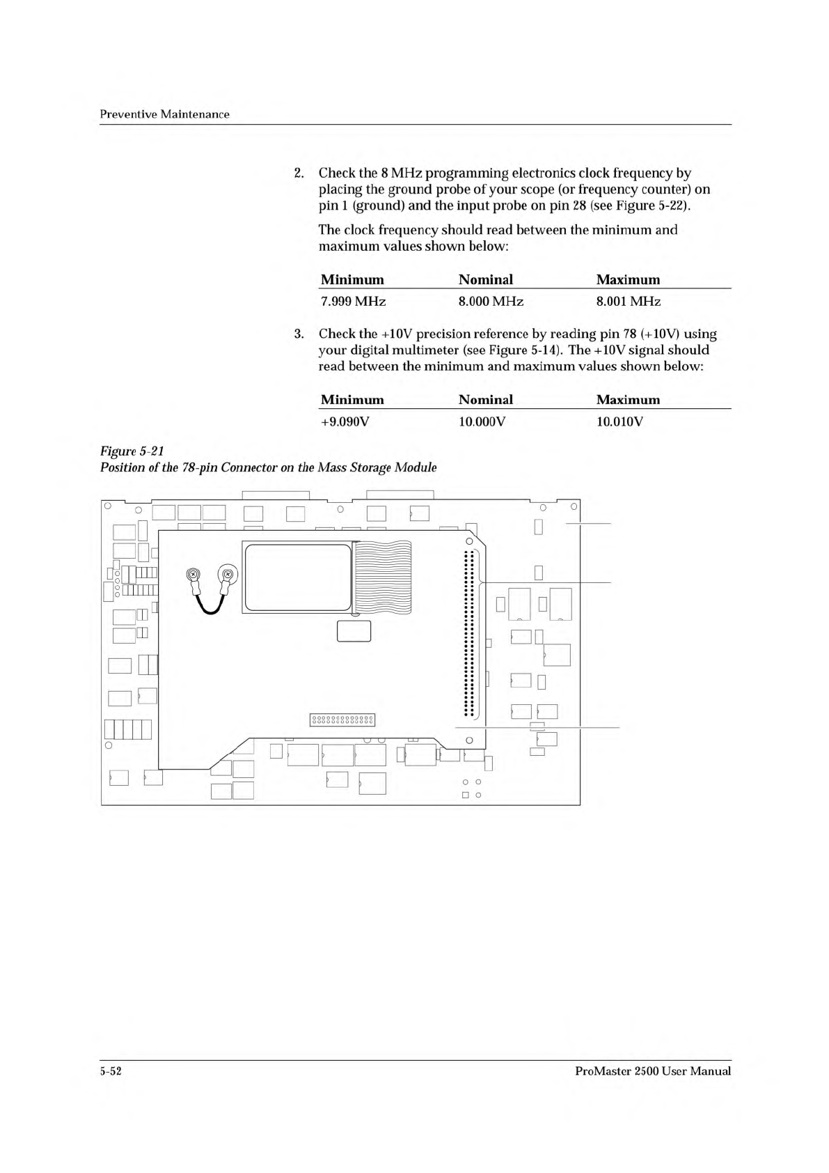
1.
Locate
the
78-pin
connector
on
the
mass
storage
module
(MSM)
board
(see
Figure
5-21).
Pins
1
and
78
are
located
on
the
lower
end
of
the
connector;
pins
39
and
40
are
at
the
high
end,
near
the
RS-
232c
connectors
on
the
controller
/waveform
board.
The
pins
that
you
will
be
checking
for
this
procedure
are
shown
in
Figure
5-21
and
are
listed
below:
•
Pin
1:
Ground
•
Pin
24:
+15V
input
supply
voltage
•
Pin
28:
8
MHz
programming
electronics
clock
•
Pin
78:
+10V
precision
reference
voltage
ProMaster
2500
User
Manual
5-51
2142-1
WAVEFORM BOARD
78-PIN CONNECTOR
MASS STORAGE
MODULE
Preventive
Maintenance
2.
Check
the
8
MHz
programming
electronics
clock
frequency
by
placing
the
ground
probe
of
your
scope
(or
frequency
counter)
on
pin
1
(ground)
and
the
input
probe
on
pin
28
(see
Figure
5-22).
The
clock
frequency
should
read
between
the
minimum
and
maximum
values
shown
below:
Minimum
Nominal
Maximum
7.999
MHz
8.000
MHz
8.001
MHz
3.
Check
the
+10V
precision
reference
by
reading
pin
78
(+10V)
using
your
digital
multimeter
(see
Figure
5-14).
The
+10V
signal
should
read
between
the
minimum
and
maximum
values
shown
below:
Minimum
Nominal
Maximum
+9.090V
10.000V
10.010V
Figure
5-21
Position
of
the
78-pin
Connector
on
the
Mass
Storage
Module
5-52
ProMaster
2500
User
Manual