2500_Users_Manual-.pdf - 第225页
7 Repair and Replacement Procedures This chapter contains instructions for replacing failed components. These component replacement procedures should be performed by qualified service personnel only. Please refer to Chap…
ALGORITHM-SPECIFIC ERROR
BEAM OPTIC MALFUNCTION
CAPACITOR CONFIGURATION
ERROR
CATEGORY X BIN NOT
AVAILABLE
DEVICE ALGORITHM NOT
FOUND
DEVICE ON THE BEAM WAS
DROPPED. CAREFULLY
REPLACE THE DEVICE ON
CHUCK OR REMOVE FROM
SYSTEM AND PRESS START
DEVICE OVERCURRENT
DEVICE ERROR CLEARED, PRESS START
Troubleshooting
A
few
devices
have
special
internal
features
or
programming
requirements
not
used
by
any
other
devices.
When
the
2500
detects
an
error
while
trying
to
access
one
of
these
unique
features,
it
issues
this
generic
error
code.
Record
the
part
number
on
the
device,
the
device
part
number
in
the
Task,
and
contact
Data
I/O
Support
(phone
numbers
listed
in
the
Preface)
for
additional
assistance.
The
beam
reference
optic
is
not
operating
correctly.
Run
the
diagnostic
tests.
Clean,
adjust,
or
replace
the
optics
(emitter
or
collector)
as
needed.
Check
the
optics
and
harness
wiring.
The
programming
module's
configuration
jumpers
are
not
located
in
the
correct
positions
for
the
device
being
programmed.
Refer
to
page
4-8
for
the
configuration
procedure.
The
system
does
not
recognize
an
output
tube
in
the
output
tube
holder.
Insert
an
output
tube
and
the
operation
should
continue.
If
it
still
fails,
check
the
microswitch
by
performing
the
output
tube
Optic
test.
Check
the
switch
and
harness
wiring.
The
device
defined
in
the
Task
was
not
found.
This
error
occurs
if
an
algorithm
update
was
installed
without
updating
the
device
list.
If
a
new
Algorithm
disk
or
disks
have
recently
been
installed,
run
the
Task
Database
Device
Check
utility
to
check
for
any
name
mismatches.
This
message
appears
if
the
beam
fails
to
correctly
pick
up
a
device.
If
possible,
place
the
device
on
the
chuck
correctly.
When
it
is
properly
replaced,
the
2500
displays:
Press
START
to
continue
the
operation.
If
the
beam
fails
to
pick
up
the
device
and
you
cannot
replace
it
on
the
chuck
properly,
remove
the
device
and
press
START.
Check
the
vacuum
in
diagnostics.
Check
for
leaks
in
the
beam
or
hoses.
Ensure
that
the
air
pressure
is
at
the
correct
setting.
The
device
in
the
programming
module
drew
excessive
current.
The
device
may
be
defective.
Inspect
the
programming
module
for
excessive
wear
to
the
block
or
deformed
module
contacts.
Replace
as
required.
6-2
ProMaster
2500
User
Manual
7
Repair
and
Replacement
Procedures
This
chapter
contains
instructions
for
replacing
failed
components.
These
component
replacement
procedures
should
be
performed
by
qualified
service
personnel
only.
Please
refer
to
Chapter
6,
“Troubleshooting,”
to
determine
which
ProMaster
2500
component
may
be
malfunctioning
and
may
require
replacement.
The
flow
chart
in
Chapter
6
will
help
you
identify
a
specific
component
failure
and
direct
you
to
the
appropriate
cleaning,
adjustment,
or
replacement
procedure.
The
replacement
procedures
are
divided
into
several
sections
and
presented
in
the
following
order:
Fuse
Replacement
7-2
Programming
Electronics
Assembly
Replacement
7-3
Motor
Replacement
7-8
Mechanical
Assembly
Removal
7-16
Solenoid
Replacement
7-19
Power
Supply
Replacement
7-19
System
Fan
Replacement
7-21
Controller
Board
Replacement
7-21
Beam
Assembly
Component
Replacement
7-22
Disk
Drive
Replacement
7-28
Keyboard/Display
Assembly
Replacement
7-29
Programmer
Module
Replacement
7-29
Assembly
Drawings
7-40
ProMaster
2500
User
Manual
7-1
1242-1
1243-1
SPARE FUSE FUSE HOLDER
Repair
and
Replacement
Procedures
Fuse
Replacement
The
main
fuse
is
located
behind
the
power
cord
input
assembly.
Perform
the
following
procedure
to
replace
the
main
fuse.
CAUTION:
For
continued
protection
against
the
possibility
of
fire,
replace
the
blown
fuse
only
with
a
fuse
of
the
same
voltage,
current,
and
type.
1.
Turn
off
the
2500
and
remove
the
power
cord.
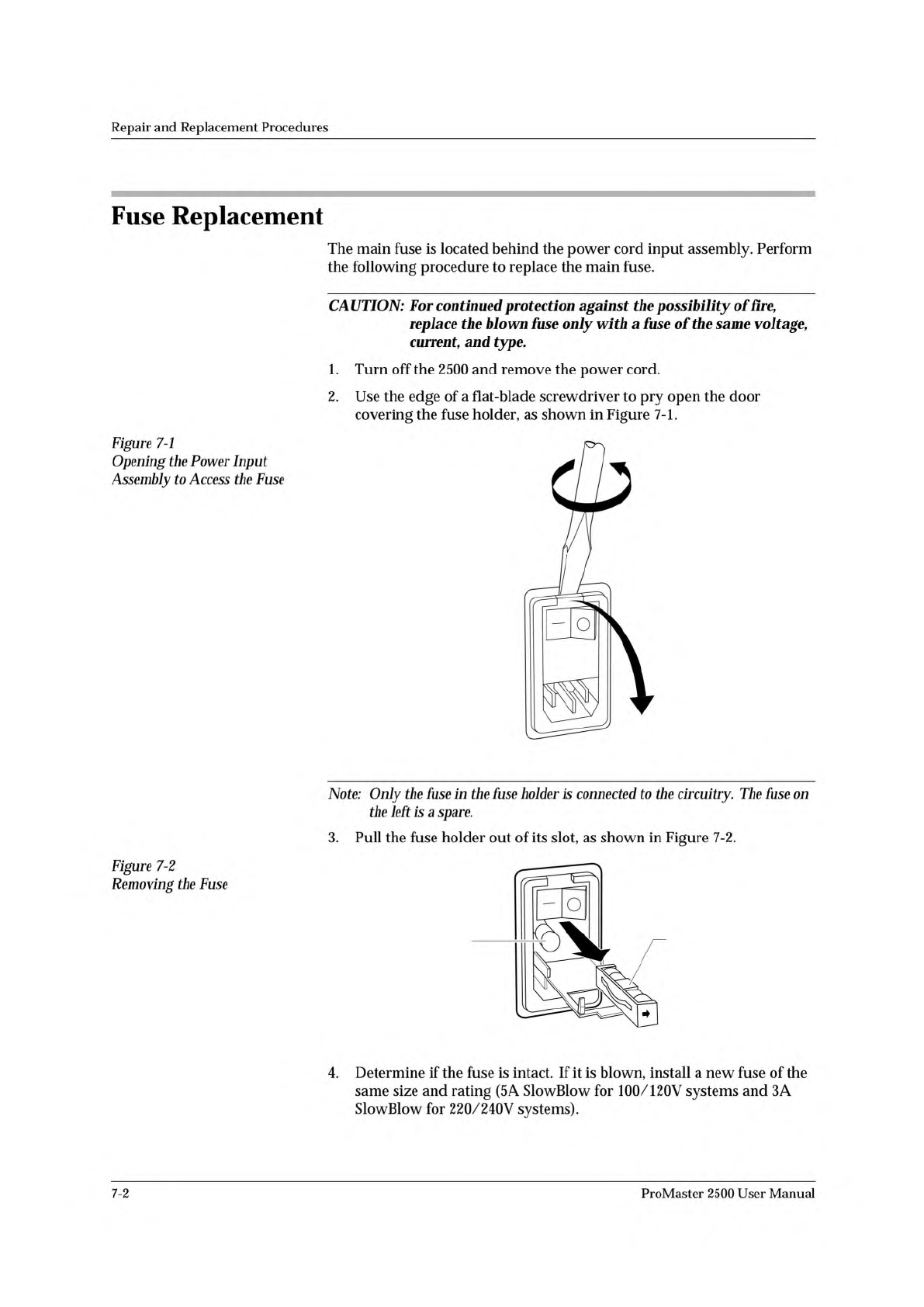
2.
Use
the
edge
of
a
flat-blade
screwdriver
to
pry
open
the
door
covering
the
fuse
holder,
as
shown
in
Figure
7-1.
Figure
7-1
Opening
the
Power
Input
Assembly
to
Access
the
Fuse
Note:
Only
the
fuse
in
the
fuse
holder
is
connected
to
the
circuitry.
The
fuse
on
the
left
is
a
spare.
3.
Pull
the
fuse
holder
out
of
its
slot,
as
shown
in
Figure
7-2.
Figure
7-2
Removing
the
Fuse
4.
Determine
if
the
fuse
is
intact.
If
it
is
blown,
install
a
new
fuse
of
the
same
size
and
rating
(5
A
SlowBlow
for
100/120V
systems
and
3A
SlowBlow
for
220/240V
systems).
7-2
ProMaster
2500
User
Manual