2500_Users_Manual-.pdf - 第228页
Repair and Replacement Procedures 5. Disconnect the red and black power cable from the connector on the left side of the controller /waveform board. (Figure 7-4 shows the location and polarity of this cable.) 7-4 ProMast…
Ω Ω
2074-2
MAIN PLATE
MAIN PLATE
SCREW (1 of 2)
HOOD
MAIN PLATE
SCREW
(2 of 2)
Repair
and
Replacement
Procedures
5.
Insert
the
fuse
holder
into
its
slot
with
the
arrow
pointing
in
the
same
direction
as
the
arrows
on
the
door
and
snap
the
door
closed.
Programming
Electronics
Assembly
Replacement
Removing
the
PE
Follow
the
steps
below
to
remove
the
PE
assembly
from
the
2500.
The
PE
assembly
is
mounted
on
the
underside
of
the
2500's
main
plate.
You
will
need
to
raise
the
main
plate
and
use
a
7/64-inch
hex
wrench
to
complete
the
removal
procedure.
WARNING:
This
procedure
should
be
performed
by
a
service
technician
trained
on
electromechanical
equipment.
Do
not
attempt
this
procedure
unless
you
are
qualified
to
do
so.
Dangerous
high
voltages
are
generated
under
the
main
plate
that
could
cause
a
harmful
electrical
shock.
Turn
off
the
2500
before
you
begin
this
procedure.
To
help
eliminate
damage
from
ESD,
wear
an
antistatic
wrist
strap
that
contains
a
IM
(minimum)
to
10M
(maximum)
isolating
resistor.
The
wrist
strap
should
be
connected
to
the
grounding
plug.
1.
Turn
off
the
2500
and
remove
the
power
cord.
2.
Remove
the
programming
module,
if
one
is
installed.
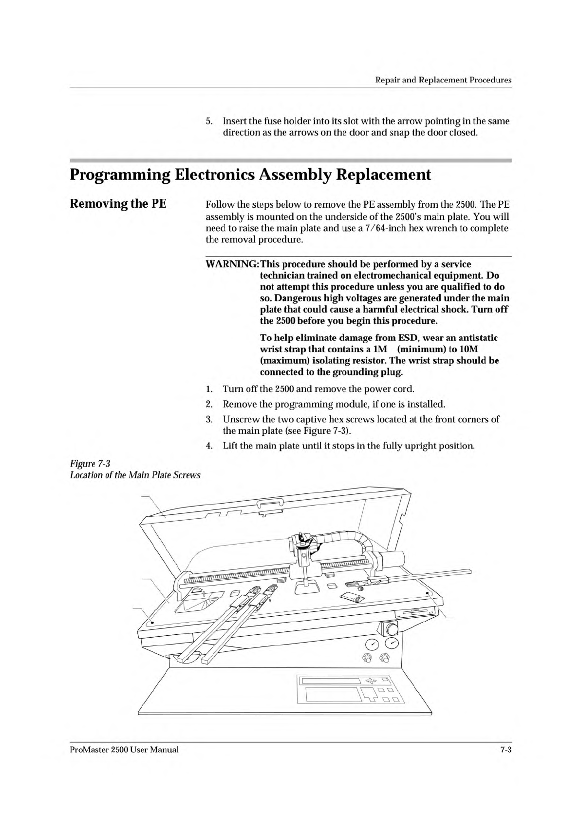
3.
Unscrew
the
two
captive
hex
screws
located
at
the
front
corners
of
the
main
plate
(see
Figure
7-3).
4.
Lift
the
main
plate
until
it
stops
in
the
fully
upright
position.
Figure
7-3
Location
of
the
Main
Plate
Screws
ProMaster
2500
User
Manual
7-3
Repair
and
Replacement
Procedures
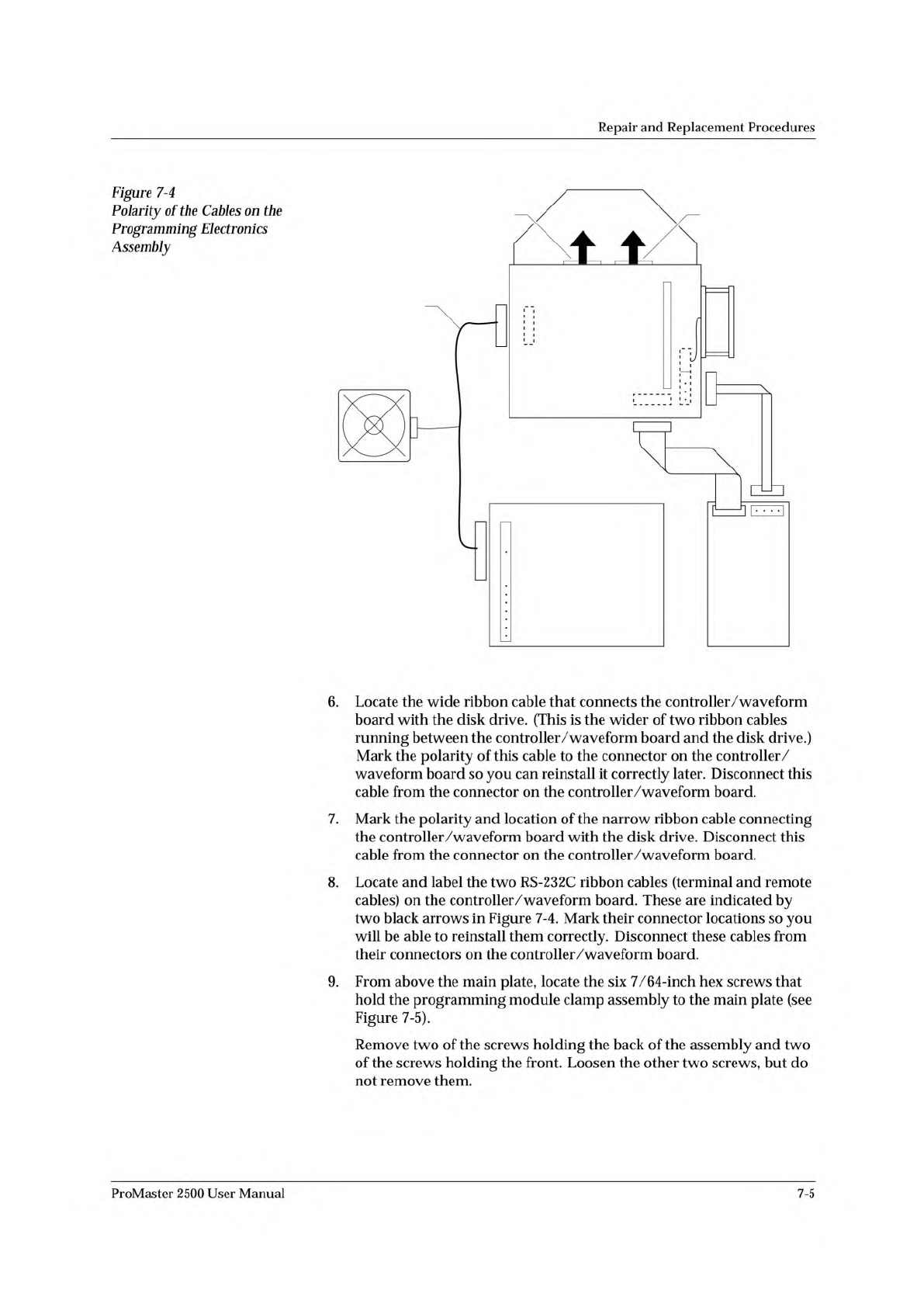
5.
Disconnect
the
red
and
black
power
cable
from
the
connector
on
the
left
side
of
the
controller
/waveform
board.
(Figure
7-4
shows
the
location
and
polarity
of
this
cable.)
7-4
ProMaster
2500
User
Manual
2056-2
DISK
DRIVE
PROGRAMMING
ELECTRONICS
POWER SUPPLY
TO MAIN
CONTROLLER
BOARD
R
R
B
B
R
R
R
(BOTTOM)
(TOP)
B
B
B
BL
R
SYSTEM FAN
CONTROLLER/
WAVEFORM
BOARD
TERMINAL REMOTE
RED AND BLACK
POWER CABLE
TO TERMINAL PORT
Repair
and
Replacement
Procedures
Figure
7-4
Polarity
of
the
Cables
on
t
加
Programming
Electronics
Assembly
6.
Locate
the
wide
ribbon
cable
that
connects
the
controller
/waveform
board
with
the
disk
drive.
(This
is
the
wider
of
two
ribbon
cables
running
between
the
controller/waveform
board
and
the
disk
drive.)
Mark
the
polarity
of
this
cable
to
the
connector
on
the
controller/
waveform
board
so
you
can
reinstall
it
correctly
later.
Disconnect
this
cable
from
the
connector
on
the
controller/waveform
board.
7.
Mark
the
polarity
and
location
of
the
narrow
ribbon
cable
connecting
the
controller/waveform
board
with
the
disk
drive.
Disconnect
this
cable
from
the
connector
on
the
controller/waveform
board.
8.
Locate
and
label
the
two
RS-
232c
ribbon
cables
(terminal
and
remote
cables)
on
the
controller/waveform
board.
These
are
indicated
by
two
black
arrows
in
Figure
7-4.
Mark
their
connector
locations
so
you
will
be
able
to
reinstall
them
correctly.
Disconnect
these
cables
from
their
connectors
on
the
controller/waveform
board.
9.
From
above
the
main
plate,
locate
the
six
7/64-inch
hex
screws
that
hold
the
programming
module
clamp
assembly
to
the
main
plate
(see
Figure
7-5).
Remove
two
of
the
screws
holding
the
back
of
the
assembly
and
two
of
the
screws
holding
the
front.
Loosen
the
other
two
screws,
but
do
not
remove
them.
ProMaster
2500
User
Manual
7-5