2500_Users_Manual-.pdf - 第236页
Repair and Replacement Procedures 10. Follow the same procedure to remove the left orbital alignment block. 11. Support the assembly with one hand while you remove the two 7/64- inch hex retaining screws (with the white …
2297-1
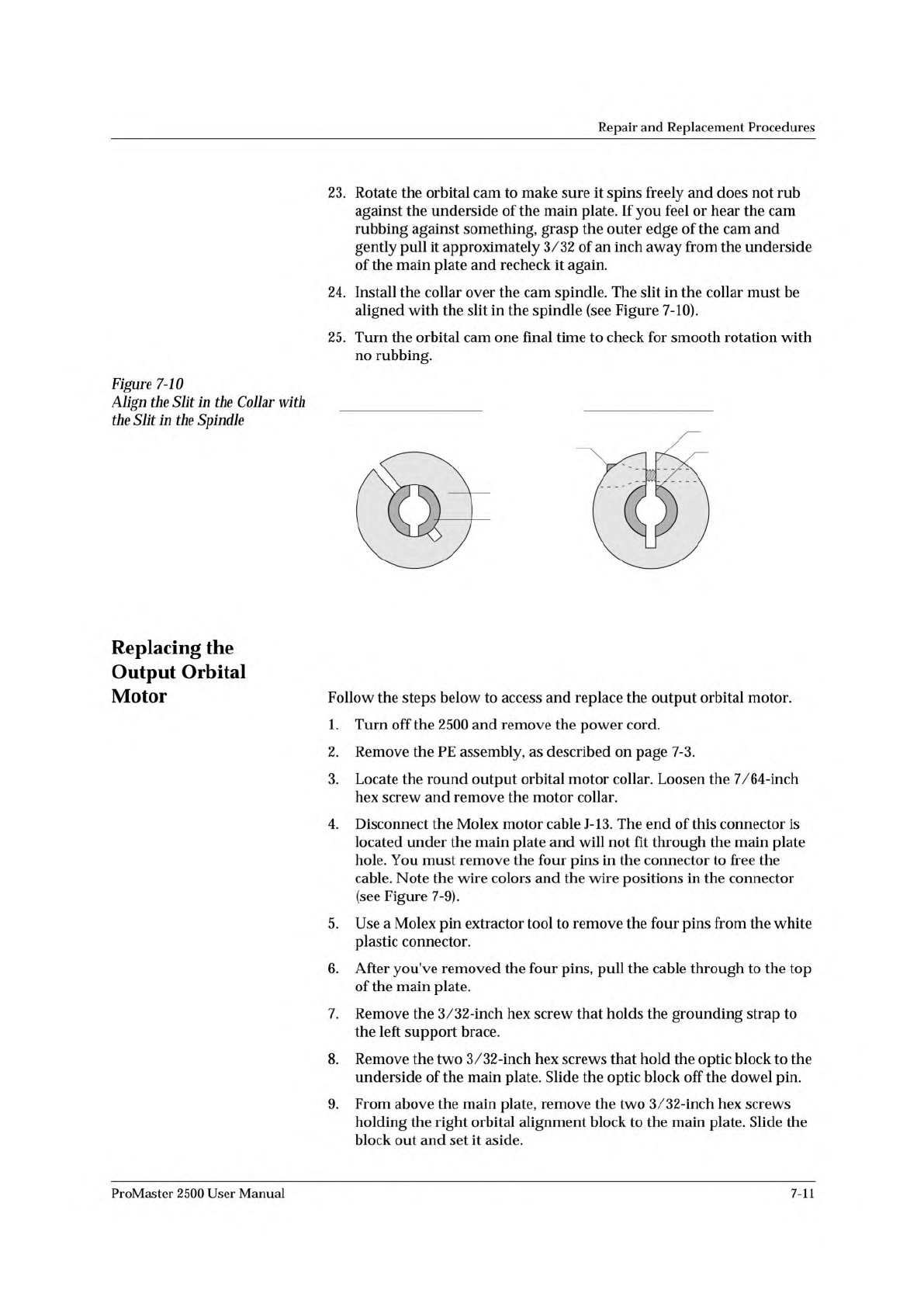
INCORRECT ALIGNMENT CORRECT ALIGNMENT
SLIT IN COLLAR
SLIT IN SPINDLE
HEX SCREW
COLLAR
SPINDLE
Repair
and
Replacement
Procedures
23.
Rotate
the
orbital
cam
to
make
sure
it
spins
freely
and
does
not
rub
against
the
underside
of
the
main
plate.
If
you
feel
or
hear
the
cam
rubbing
against
something,
grasp
the
outer
edge
of
the
cam
and
gently
pull
it
approximately
3/32
of
an
inch
away
from
the
underside
of
the
main
plate
and
recheck
it
again.
24.
Install
the
collar
over
the
cam
spindle.
The
slit
in
the
collar
must
be
aligned
with
the
slit
in
the
spindle
(see
Figure
7-10).
25.
Turn
the
orbital
cam
one
final
time
to
check
for
smooth
rotation
with
no
rubbing.
Figure
7-10
Align
the
Slit
历
the
Collar
with
the
Slit
加
the
Spindle
Replacing
the
Output
Orbital
Motor
Follow
the
steps
below
to
access
and
replace
the
output
orbital
motor.
1.
Turn
off
the
2500
and
remove
the
power
cord.
2.
Remove
the
PE
assembly,
as
described
on
page
7-3.
3.
Locate
the
round
output
orbital
motor
collar.
Loosen
the
7/64-inch
hex
screw
and
remove
the
motor
collar.
4.
Disconnect
the
Molex
motor
cable
J-
13.
The
end
of
this
connector
is
located
under
the
main
plate
and
will
not
fit
through
the
main
plate
hole.
You
must
remove
the
four
pins
in
the
connector
to
free
the
cable.
Note
the
wire
colors
and
the
wire
positions
in
the
connector
(see
Figure
7-9).
5.
Use
a
Molex
pin
extractor
tool
to
remove
the
four
pins
from
the
white
plastic
connector.
6.
After
you've
removed
the
four
pins,
pull
the
cable
through
to
the
top
of
the
main
plate.
7.
Remove
the
3
/32
-inch
hex
screw
that
holds
the
grounding
strap
to
the
left
support
brace.
8.
Remove
the
two
3/32-inch
hex
screws
that
hold
the
optic
block
to
the
underside
of
the
main
plate.
Slide
the
optic
block
off
the
dowel
pin.
9.
From
above
the
main
plate,
remove
the
two
3/32-inch
hex
screws
holding
the
right
orbital
alignment
block
to
the
main
plate.
Slide
the
block
out
and
set
it
aside.
ProMaster
2500
User
Manual
7-11
Repair
and
Replacement
Procedures
10.
Follow
the
same
procedure
to
remove
the
left
orbital
alignment
block.
11.
Support
the
assembly
with
one
hand
while
you
remove
the
two
7/64-
inch
hex
retaining
screws
(with
the
white
plastic
standoff)
on
the
tube
clamp
support
braces.
12.
Carefully
slide
the
back
end
of
the
orbital
assembly
off
the
orbital
cam
spindle.
Be
careful
that
the
white
bushing
between
these
two
is
not
lost
or
damaged.
13.
When
the
assembly
is
off
the
spindle,
slide
the
entire
assembly
toward
the
back
of
the
2500
until
it
is
free
from
the
two
front
support
braces.
Let
the
assembly
dangle
from
the
cables.
14.
Remove
the
orbital
cam
from
the
motor
shaft.
Now
you
are
ready
to
remove
the
output
orbital
motor.
15.
From
below
the
main
plate,
remove
the
four
1/16-inch
hex
screws
that
holds
the
output
orbital
motor
to
the
main
plate.
16.
Lower
the
main
plate
and
remove
the
output
orbital
motor.
17.
Place
the
new
output
orbital
motor
in
position
on
the
main
plate.
Make
sure
the
power
cable
is
oriented
to
the
right
side
of
the
new
output
orbital
motor.
18.
Guide
the
motor
cable
through
the
hole
in
the
main
plate.
19.
Insert
the
four
motor
wires
into
the
white
plastic
Molex
connector.
Be
sure
to
insert
the
wires
in
the
same
order
(and
orientation)
as
shown
in
Figure
7-9.
20.
The
output
orbital
motor
shaft
has
a
flat
edge
on
one
side.
Turn
the
shaft
until
the
flat
edge
faces
the
front
of
the
2500.
21.
The
orbital
cam
has
a
small
hole
on
its
outer
edge.
Position
the
cam
on
the
motor
shaft
so
this
small
hole
is
positioned
on
the
right
side
(input
side)
of
the
shaft.
CAUTION:
When
you
re
加
sta
〃仍
e
orbital
assembly,
make
sure
the
white
bushing
that
fits
over
the
spindle
stays
加
position.
22.
Reinstall
the
assembly
(in
reverse
order
from
the
procedure
in
steps
11-13
above).
23.
Reinstall
the
left
and
right
alignment
blocks
and
the
optic
block.
24.
Rotate
the
orbital
cam
to
make
sure
it
spins
freely
and
does
not
rub
against
the
underside
of
the
main
plate.
If
you
feel
or
hear
the
cam
rubbing
against
something,
grasp
the
outer
edge
of
the
cam
and
gently
pull
it
approximately
3/32
of
an
inch
away
from
the
underside
of
the
main
plate
and
recheck
it
again.
25.
Install
the
collar
over
the
cam
spindle.
The
slit
in
the
collar
must
be
aligned
with
the
slit
in
the
spindle
(see
Figure
7-10).
26.
Turn
the
orbital
cam
one
final
time
to
check
for
smooth
rotation
with
no
rubbing.
7-12
ProMaster
2500
User
Manual
2310-1
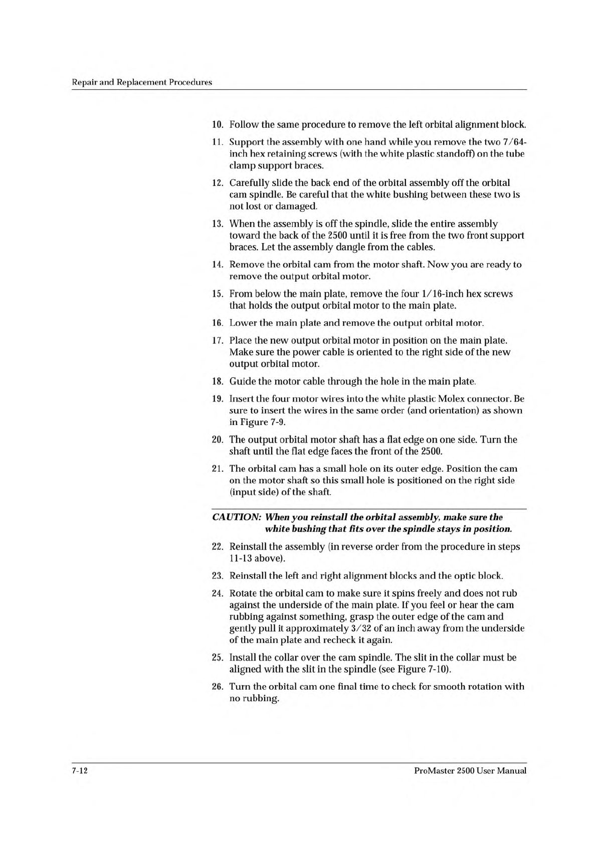
PRINT DRIVE
MOTOR
SCREW (1 of 4)
Repair
and
Replacement
Procedures
Replacing
the
Print
Drive
Motor
Follow
the
steps
below
to
replace
the
print
drive
motor.
1.
Turn
off
the
2500
and
remove
the
power
cord.
2.
Unplug
the
motor
cable
from
the
motor
power
supply.
3.
Push
down
on
the
belt
tension
wheel
and
remove
the
drive
belt.
4.
Loosen
the
5/64-labeler
knob
set
screw
(two
screws
are
used
on
the
thermal
printer)
and
pull
the
knob
off
the
motor
shaft.
5.
Remove
the
four
3/32-inch
hex
screws
that
hold
the
motor
to
the
labeler
plate
and
remove
the
motor.
See
Figure
7-11.
6.
Install
the
new
motor
and
reinstall
all
the
components
you
removed.
Figure
7-11
Removing
the
Print
Drive
Motor
(Dot
Matrix
Printer
shown;
Thermal
Printer
similar)
Replacing
the
Dot
Matrix
Print
Head
Follow
the
steps
below
to
replace
the
print
head.
If
you
need
to
adjust
the
gap
between
the
platen
and
the
print
head,
refer
to
the
“Adjusting
the
Print
Head
Gap”
procedure
on
page
5-24.
The
impact
print
head
is
mounted
on
a
small
printed
circuit
board
(PCB).
Do
not
attempt
to
remove
the
print
head
from
the
PCB.
The
new
print
head
is
mounted
on
a
new
board,
which
should
be
installed
as
one
assembly.
1.
Turn
off
the
2500
and
remove
the
power
cord.
2.
Use
a
3/32-inch
hex
wrench
to
remove
the
two
hex
screws
that
hold
the
print
head
to
the
print
head
mounting
blocks.
3.
Remove
the
two
cables
(J-22
and
J-23)
from
the
cable
connectors
on
the
print
head
PCB.
ProMaster
2500
User
Manual
Note:
Identify
and
mark
the
polarity
of
the
cables
before
you
remove
them.
4.
Install
the
new
print
head
assembly.
7-13