2500_Users_Manual-.pdf - 第241页
2309-1 OUTPUT ORBITAL ASSEMBLY SPRING (1 of 4) CENTER POST (1 of 2) Repair and Replacement Procedures 11. Carefully pull the input orbital assembly off the motor spindle and then slide the assembly to the left, until the…
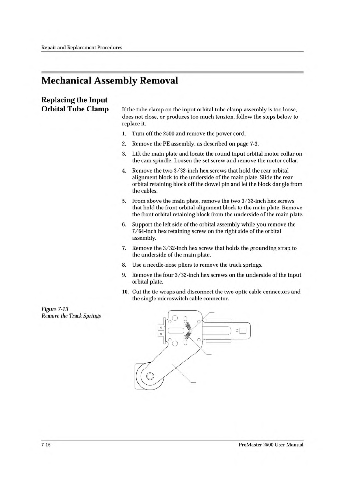
2308-1
INPUT ORBITAL
ASSEMBLY
SPRING (1 of 2)
CENTER POST
Repair
and
Replacement
Procedures
Mechanical
Assembly
Removal
Replacing
the
Input
Orbital
Tube
Clamp
Figure
7-13
Remove
the
Track
Springs
If
the
tube
clamp
on
the
input
orbital
tube
clamp
assembly
is
too
loose,
does
not
close,
or
produces
too
much
tension,
follow
the
steps
below
to
replace
it.
1.
Turn
off
the
2500
and
remove
the
power
cord.
2.
Remove
the
PE
assembly,
as
described
on
page
7-3.
3.
Lift
the
main
plate
and
locate
the
round
input
orbital
motor
collar
on
the
cam
spindle.
Loosen
the
set
screw
and
remove
the
motor
collar.
4.
Remove
the
two
3/32-inch
hex
screws
that
hold
the
rear
orbital
alignment
block
to
the
underside
of
the
main
plate.
Slide
the
rear
orbital
retaining
block
off
the
dowel
pin
and
let
the
block
dangle
from
the
cables.
5.
From
above
the
main
plate,
remove
the
two
3/32-inch
hex
screws
that
hold
the
front
orbital
alignment
block
to
the
main
plate.
Remove
the
front
orbital
retaining
block
from
the
underside
of
the
main
plate.
6.
Support
the
left
side
of
the
orbital
assembly
while
you
remove
the
7/64-inch
hex
retaining
screw
on
the
right
side
of
the
orbital
assembly.
7.
Remove
the
3/32-inch
hex
screw
that
holds
the
grounding
strap
to
the
underside
of
the
main
plate.
8.
Use
a
needle-nose
pliers
to
remove
the
track
springs.
9.
Remove
the
four
3/32-inch
hex
screws
on
the
underside
of
the
input
orbital
plate.
10.
Cut
the
tie
wraps
and
disconnect
the
two
optic
cable
connectors
and
the
single
microswitch
cable
connector.
7-16
ProMaster
2500
User
Manual
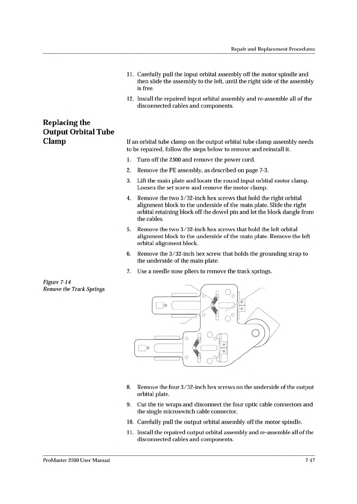
2309-1
OUTPUT ORBITAL
ASSEMBLY
SPRING (1 of 4)
CENTER POST (1 of 2)
Repair
and
Replacement
Procedures
11.
Carefully
pull
the
input
orbital
assembly
off
the
motor
spindle
and
then
slide
the
assembly
to
the
left,
until
the
right
side
of
the
assembly
is
free.
12.
Install
the
repaired
input
orbital
assembly
and
re-assemble
all
of
the
disconnected
cables
and
components.
Replacing
the
Output
Orbital
Tube
Clamp
Figure
7-14
Remove
the
Track
Springs
If
an
orbital
tube
clamp
on
the
output
orbital
tube
clamp
assembly
needs
to
be
repaired,
follow
the
steps
below
to
remove
and
reinstall
it.
1.
Turn
off
the
2500
and
remove
the
power
cord.
2.
Remove
the
PE
assembly,
as
described
on
page
7-3.
3.
Lift
the
main
plate
and
locate
the
round
input
orbital
motor
clamp.
Loosen
the
set
screw
and
remove
the
motor
clamp.
4.
Remove
the
two
3/32-inch
hex
screws
that
hold
the
right
orbital
alignment
block
to
the
underside
of
the
main
plate.
Slide
the
right
orbital
retaining
block
off
the
dowel
pin
and
let
the
block
dangle
from
the
cables.
5.
Remove
the
two
3/32-inch
hex
screws
that
hold
the
left
orbital
alignment
block
to
the
underside
of
the
main
plate.
Remove
the
left
orbital
alignment
block.
6.
Remove
the
3/32-inch
hex
screw
that
holds
the
grounding
strap
to
the
underside
of
the
main
plate.
7.
Use
a
needle
nose
pliers
to
remove
the
track
springs.
8.
Remove
the
four
3/32-inch
hex
screws
on
the
underside
of
the
output
orbital
plate.
9.
Cut
the
tie
wraps
and
disconnect
the
four
optic
cable
connectors
and
the
single
microswitch
cable
connector.
10.
Carefully
pull
the
output
orbital
assembly
off
the
motor
spindle.
1
1.
Install
the
repaired
output
orbital
assembly
and
re-assemble
all
of
the
disconnected
cables
and
components.
ProMaster
2500
User
Manual
7-17
Repair
and
Replacement
Procedures
Replacing
the
Programming
Module
Clamp
Air
Cylinder
If
the
programming
module
clamp
air
cylinder
fails,
follow
the
steps
below
to
replace
it.
1.
Turn
off
the
2500
and
remove
the
power
cord.
2.
From
above
the
main
plate,
remove
four
of
the
six
7/64-inch
hex
screws
(two
front
ones
and
two
back
ones)
holding
the
programming
module
clamp
assembly
to
the
main
plate.
3.
Holding
the
PE
from
the
bottom
(below
the
main
plate),
remove
the
other
two
screws.
Lower
the
programming
module
clamp
assembly
and
let
it
rest
on
the
black
protective
shield.
4.
Remove
the
two
blue
and
two
red
air
lines
from
the
four
quick
connects,
noting
their
positions
for
reinstallation.
5.
Remove
the
retaining
bar.
This
bar
holds
the
programming
electronics
assembly
in
place
on
the
underside
of
the
main
plate.
Use
a
7/64-inch
hex
wrench
to
remove
the
two
hex
screws
that
hold
the
bar
in
place.
Set
them
in
a
safe
place
to
use
when
you
reinstall
the
assembly.
6.
Use
a
wrench
to
remove
the
air
cylinder
nut,
then
pull
the
air
cylinder
away
from
the
programming
module
clamp
assembly.
7.
Install
the
new
air
cylinder.
8.
Ensure
that
the
clamps
pull
back
far
enough
to
clear
the
inside
wall
when
retracted.
If
not,
loosen
the
locking
nut
attaching
the
cylinder
shaft
to
the
back
of
the
clamp.
Using
a
small
pair
of
needle-nose
pliers,
turn
the
shaft
further
into
the
clamp.
Tighten
the
locking
nut
when
the
clamps
pull
back
far
enough.
9.
Reinstall
all
of
the
removed
components.
10.
Reinstall
the
programming
module
clamp
assembly
and
reconnect
the
air
lines.
7-18
ProMaster
2500
User
Manual