2500_Users_Manual-.pdf - 第244页
Repair and Replacement Procedures Replacing the PE Power Supply If the programming electronics power supply fails, follow the steps below to replace it. 1. Turn off the 2500 and remove the power cord. 2. Disconnect the t…
2312-1
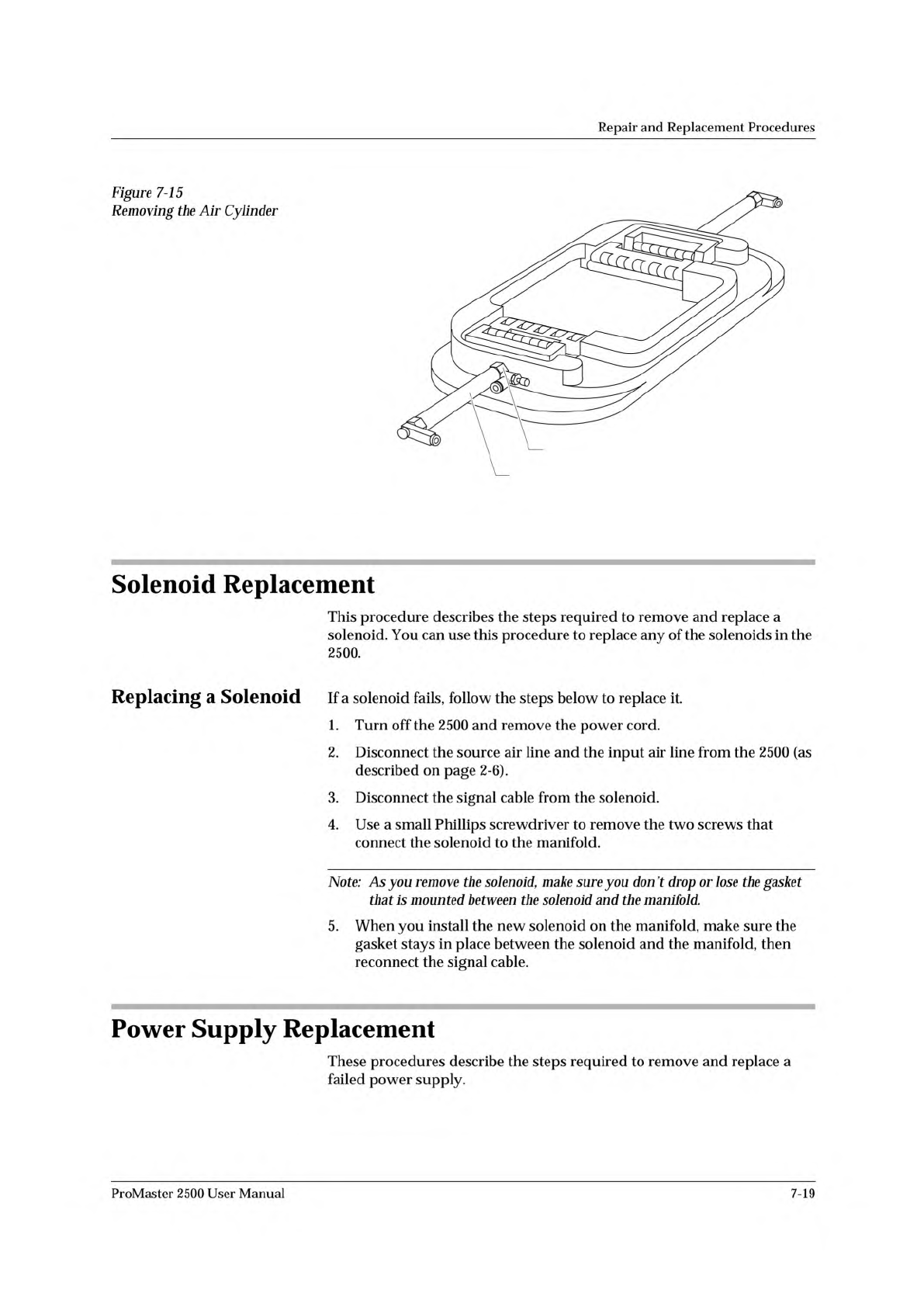
AIR CYLINDER NUT
AIR CYLINDER
Repair
and
Replacement
Procedures
Figure
7-15
Removing
the
Air
Cylinder
Solenoid
Replacement
This
procedure
describes
the
steps
required
to
remove
and
replace
a
solenoid.
You
can
use
this
procedure
to
replace
any
of
the
solenoids
in
the
2500.
Replacing
a
Solenoid
If
a
solenoid
fails,
follow
the
steps
below
to
replace
it.
1.
Turn
off
the
2500
and
remove
the
power
cord.
2.
Disconnect
the
source
air
line
and
the
input
air
line
from
the
2500
(as
described
on
page
2-6).
3.
Disconnect
the
signal
cable
from
the
solenoid.
4.
Use
a
small
Phillips
screwdriver
to
remove
the
two
screws
that
connect
the
solenoid
to
the
manifold.
Note:
As
you
remove
the
solenoid,
make
sure
you
don't
drop
or
lose
the
gasket
that
is
mounted
between
the
solenoid
and
the
manifold.
5.
When
you
install
the
new
solenoid
on
the
manifold,
make
sure
the
gasket
stays
in
place
between
the
solenoid
and
the
manifold,
then
reconnect
the
signal
cable.
Power
Supply
Replacement
These
procedures
describe
the
steps
required
to
remove
and
replace
a
failed
power
supply.
ProMaster
2500
User
Manual
7-19
Repair
and
Replacement
Procedures
Replacing
the
PE
Power
Supply
If
the
programming
electronics
power
supply
fails,
follow
the
steps
below
to
replace
it.
1.
Turn
off
the
2500
and
remove
the
power
cord.
2.
Disconnect
the
two
cable
connectors.
3.
Remove
the
four
1/4-inch
hex
nuts
at
the
corners
of
the
assembly.
4.
Carefully
lift
out
the
PE
power
supply
assembly.
5.
Install
the
new
PE
power
supply
and
reconnect
the
cables.
Replacing
the
Toroid
Transformer
If
the
Toroid
transformer
fails,
follow
the
steps
below
to
replace
it.
1.
Turn
off
the
2500
and
remove
the
power
cord.
2.
Disconnect
the
two
cable
connectors
JI
and
J3.
3.
Remove
the
single
3/16-inch
hex
mounting
screw.
4.
The
Toroid
transformer
is
heavy;
lift
it
out
carefully.
5.
Install
the
new
Toroid
transformer
and
reconnect
the
cables.
Replacing
the
Toroid
PCB
If
the
Toroid
PCB
fails,
follow
the
steps
below
to
replace
it.
1.
Turn
off
the
2500
and
remove
the
power
cord.
2.
Disconnect
the
four
cables
in
connectors
J-l
through
J-4.
3.
Remove
the
four
1/4-inch
hex
nuts
at
the
corners
of
the
board.
4.
Hold
the
edges
of
the
board,
do
not
touch
the
capacitors,
and
lift
the
board
straight
up.
You
may
damage
the
capacitors
if
you
apply
pressure
to
them.
5.
Install
the
new
Toroid
PCB
power
supply
board
and
reconnect
the
cables.
6.
Check
the
voltage
selection
switch.
Replacing
the
Controller
Power
Supply
If
the
controller
power
supply
fails,
follow
the
steps
below
to
replace
it.
1.
Turn
off
the
2500
and
remove
the
power
cord.
2.
Disconnect
the
two
cable
connectors.
3.
Remove
the
four
1/4-inch
hex
nuts
at
the
corners
of
the
board.
4.
Carefully
lift
out
the
controller
power
supply
board.
5.
Install
the
new
controller
power
supply
and
reconnect
the
cables.
6.
Check
the
voltage
selection
jumper.
7-20
ProMaster
2500
User
Manual
Repair
and
Replacement
Procedures
Replacing
the
Labeler
Power
Supply
If
the
labeler
power
supply
fails,
follow
the
steps
below
to
replace
it.
Be
sure
to
note
the
direction
of
rotation
before
you
remove
the
fan
so
that
you
can
reinstall
it
correctly.
1.
2.
Turn
off
the
2500
and
remove
the
power
cord.
Disconnect
the
three
AC
input
cables
on
the
right
side
of
the
power
supply
assembly.
3.
Disconnect
the
two
output
cables
on
the
left
side
of
the
power
supply
assembly.
4.
Use
a
3/32-inch
hex
wrench
to
remove
the
two
mounting
screws
from
the
back
panel
of
the
2500.
5.
6.
Carefully
lift
out
the
labeler
power
supply
assembly.
Install
the
new
labeler
power
supply
assembly,
reconnect
the
cables,
and
reinstall
the
mounting
screws.
System
Fan
Replacement
This
procedure
describes
the
steps
required
to
remove
and
replace
the
system
fan.
Replacing
the
System
Fan
If
the
system
fan
fails,
follow
the
steps
below
to
replace
it.
1.
2.
3.
4.
Turn
off
the
2500
and
remove
the
power
cord.
Remove
the
four
7/64-inch
hex
screws.
Carefully
lift
out
the
system
fan.
Install
the
new
system
fan
and
reconnect
the
power
cable.
Controller
Board
Replacement
This
procedure
describes
the
steps
required
to
remove
and
replace
the
controller
board.
Replacing
the
Controller
Board
If
the
controller
board
fails,
follow
the
steps
below
to
replace
it.
Make
sure
you
observe
all
static
safety
precautions.
1.
2.
Turn
off
the
2500
and
remove
the
power
cord.
Note
the
positions
and
polarities
of
all
of
the
cables
connected
to
the
controller
board
before
you
disconnect
any
of
the
cable
connectors.
3.
Disconnect
all
of
the
cable
connectors.
ProMaster
2500
User
Manual
7-21