2500_Users_Manual-.pdf - 第248页
Repair and Replacement Procedures 9. The right lead screw bearing assembly will come away from the right end plate with the lead screw. Remove the bearing assembly and replace it with a new bearing assembly. 10. Reverse …
2389-1
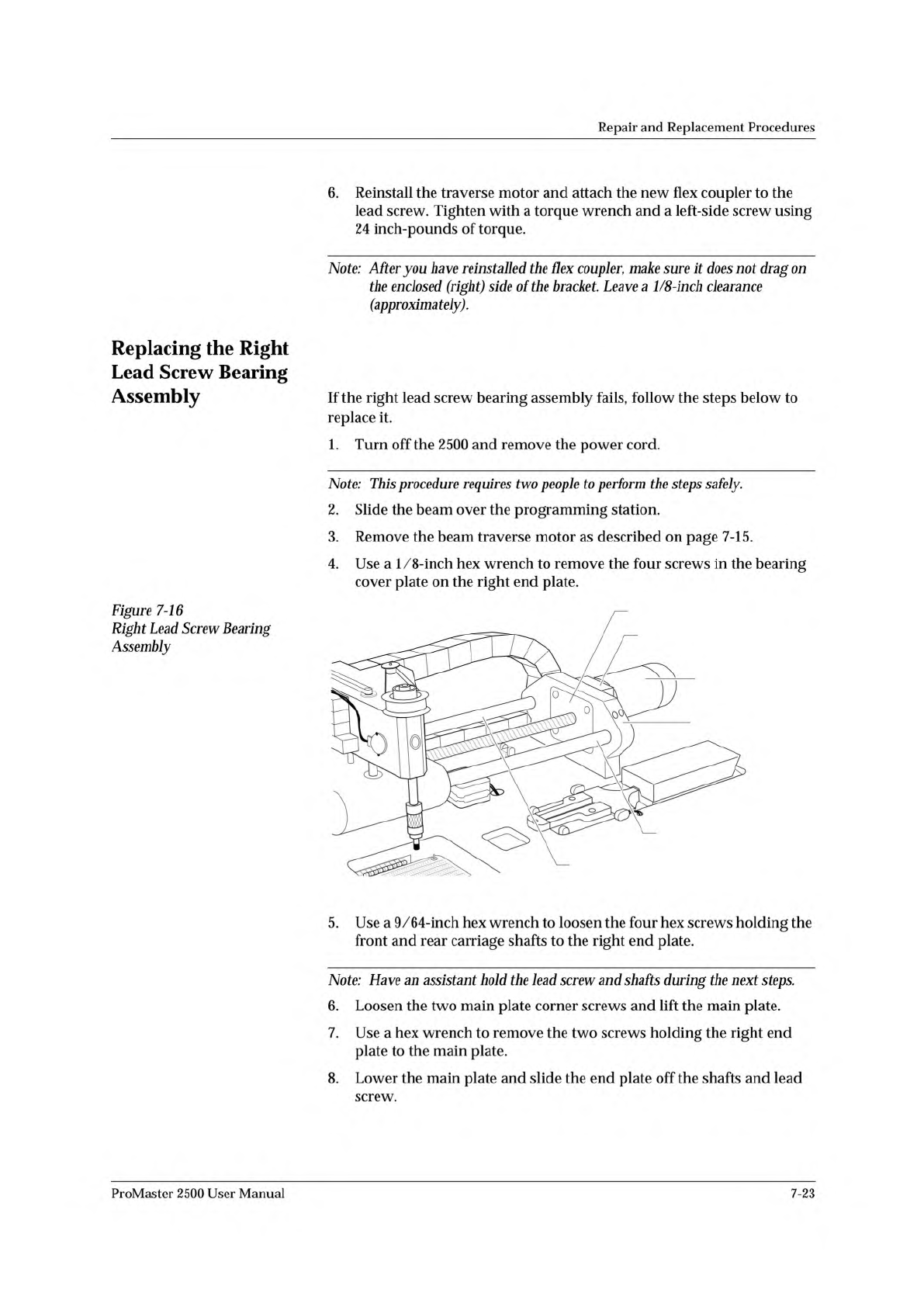
BEAM TRAVERSE
MOUNTING BLOCK
RIGHT END PLATE
BEARING COVER PLATE
BEAM TRAVERSE
MOTOR
REAR CARRIAGE SHAFT
FRONT COVER SHAFT
Repair
and
Replacement
Procedures
6.
Reinstall
the
traverse
motor
and
attach
the
new
flex
coupler
to
the
lead
screw.
Tighten
with
a
torque
wrench
and
a
left-side
screw
using
24
inch-pounds
of
torque.
Note:
After
you
have
reinstalled
the
Hex
coupler,
make
sure
it
does
not
drag
on
the
enclosed
(right)
side
of
the
bracket.
Leave
a
1/8-inch
clearance
(approximately).
Replacing
the
Right
Lead
Screw
Bearing
Assembly
Figure
7-16
Right
Lead
Screw
Bearing
Assembly
If
the
right
lead
screw
bearing
assembly
fails,
follow
the
steps
below
to
replace
it.
1.
Turn
off
the
2500
and
remove
the
power
cord.
Note:
This
procedure
requires
two
people
to
perform
the
steps
safely.
2.
Slide
the
beam
over
the
programming
station.
3.
Remove
the
beam
traverse
motor
as
described
on
page
7-15.
4.
Use
a
1/8-inch
hex
wrench
to
remove
the
four
screws
in
the
bearing
cover
plate
on
the
right
end
plate.
5.
Use
a
9/64-inch
hex
wrench
to
loosen
the
four
hex
screws
holding
the
front
and
rear
carriage
shafts
to
the
right
end
plate.
Note:
Have
an
assistant
hold
the
lead
screw
and
shafts
during
the
next
steps.
6.
Loosen
the
two
main
plate
corner
screws
and
lift
the
main
plate.
7.
Use
a
hex
wrench
to
remove
the
two
screws
holding
the
right
end
plate
to
the
main
plate.
8.
Lower
the
main
plate
and
slide
the
end
plate
off
the
shafts
and
lead
screw.
ProMaster
2500
User
Manual
7-23
Repair
and
Replacement
Procedures
9.
The
right
lead
screw
bearing
assembly
will
come
away
from
the
right
end
plate
with
the
lead
screw.
Remove
the
bearing
assembly
and
replace
it
with
a
new
bearing
assembly.
10.
Reverse
the
procedure
to
reinstall
all
of
the
components.
Replacing
the
Left
Lead
Screw
Bearing
Assembly
Replacing
the
Lead
Screw
If
the
left
lead
screw
bearing
assembly
fails,
follow
the
steps
below
to
replace
it.
1.
Turn
off
the
2500
and
remove
the
power
cord.
Note:
This
procedure
requires
two
people
to
perform
the
steps
safely.
2.
Slide
the
beam
over
the
programming
station.
3.
Use
a
1/8-inch
hex
wrench
to
remove
the
four
screws
in
the
bearing
cover
plate
on
the
left
end
plate.
4.
Use
a
9/64-inch
hex
wrench
to
loosen
the
four
hex
screws
holding
the
front
and
rear
carriage
shafts
to
the
left
end
plate.
Note:
Have
an
assistant
hold
the
lead
screw
and
shafts
during
the
next
steps.
5.
Loosen
the
two
main
plate
corner
screws
and
lift
the
main
plate.
6.
Use
a
hex
wrench
to
remove
the
two
screws
holding
the
left
end
plate
to
the
main
plate.
7.
Lower
the
main
plate
and
slide
the
end
plate
off
the
shafts
and
lead
screw.
8.
The
left
lead
screw
bearing
assembly
will
come
away
from
the
left
end
plate
with
the
lead
screw.
Remove
the
bearing
assembly
and
replace
it
with
a
new
bearing
assembly.
9.
Reverse
the
procedure
to
reinstall
all
of
the
components.
If
the
lead
screw
is
damaged,
follow
the
steps
below
to
replace
it.
1.
Turn
off
the
2500
and
remove
the
power
cord.
2.
Slide
the
beam
over
the
programming
station.
Note:
This
procedure
requires
two
people
to
perform
the
steps
safely.
3.
Look
through
the
two
holes
in
the
top
of
the
beam
traverse
motor's
mounting
block
while
you
manually
rotate
the
lead
screw
until
the
heads
of
the
flex
coupler
set
screws
are
visible
through
the
holes.
4.
Use
a
7/64-inch
hex
wrench
to
remove
the
set
screw
on
the
left
side
of
the
flex
coupler.
5.
Use
a
1/8-inch
hex
wrench
to
remove
the
four
screws
in
the
bearing
cover
plate
on
the
left
end
plate.
7-24
ProMaster
2500
User
Manual
Repair
and
Replacement
Procedures
6.
Use
a
9/64-inch
hex
wrench
to
loosen
the
four
hex
screws
holding
the
front
and
rear
carriage
shafts
to
the
left
end
plate.
Note:
Have
an
assistant
hold
the
lead
screw
and
shafts
during
the
next
steps.
7.
Loosen
the
two
main
plate
corner
screws
and
lift
the
main
plate.
8.
Use
a
hex
wrench
to
remove
the
two
screws
holding
the
left
end
plate
to
the
main
plate.
9.
Lower
the
main
plate
and
slide
the
end
plate
off
the
shafts
and
lead
screw.
10.
Twist
the
lead
screw
until
it
pulls
away
from
the
beam
traverse
motor.
Walk
the
lead
screw
through
the
beam,
then
slide
it
away
from
the
2500
through
the
left
endplate.
Note:
Make
sure
the
anti-backlash
nut
remains
intact
when
you
remove
the
lead
screw.
1
1.
Reinstall
the
lead
screw
and
all
of
the
removed
components.
12.
Lubricate
the
screw
as
described
on
page
5-63.
Replacing
the
Anti¬
backlash
Nut
If
the
anti-backlash
nut
is
damaged,
follow
the
steps
below
to
replace
it.
1.
Remove
the
lead
screw
(as
described
in
steps
1
through
10
on
page
7-24)
and
carefully
set
it
aside.
2.
Use
a
5/64-inch
hex
wrench
to
remove
the
two
screws
that
hold
the
limit
bar
to
the
beam
shafts
(see
Figure
7-17).
3.
Pull
the
beam
up
and
away
from
the
beam
shafts.
Leave
all
of
the
cables
connected
and
carefully
set
the
beam
aside.
4.
Use
a
9/64-inch
hex
wrench
to
remove
the
four
screws
that
hold
the
front
carriage
shaft
in
place.
Note:
There
are
two
9/64-inch
hex
screws
at
the
front
of
the
left
end
plate
and
two
9/64-inch
hex
screws
at
the
front
of
the
right
end
plate.
5.
Support
the
carriage
while
you
slide
the
front
carriage
shaft
through
the
carriage.
Set
the
front
carriage
shaft
aside.
6.
Use
a
9/64-inch
hex
wrench
to
remove
the
four
screws
that
hold
the
rear
carriage
shaft
in
place
(this
is
similar
to
step
4,
above).
7.
Support
the
carriage
while
you
slide
the
rear
carriage
shaft
through
the
carriage.
Set
the
rear
carriage
shaft
aside.
8.
From
the
left
side
of
carriage,
insert
the
anti-backlash
nut
removal
tool
into
the
anti-backlash
nut
and
twist
it
counterclockwise.
As
you
twist,
the
anti-backlash
nut
will
protrude
from
the
right
side
of
the
carriage.
Guide
it
out
with
your
hand.
Note:
You
may
need
to
use
a
wrench
to
break
the
anti-backlash
nut
free.
ProMaster
2500
User
Manual
7-25