2500_Users_Manual-.pdf - 第253页
Repair and Replacement Procedures Keyboard/Display Assembly Replacement This procedure describes the steps required to remove and replace the keyboard /display assembly. Replacing the Keyboard/Display Assembly If the key…
LO QUICK
CONNECT
(Gray)
HI QUICK
CONNECT (Black)
E CHAIN SCREWS
2338-1
1/4"
SCREWS
1
11
15 5 8 13
19
21
17
1274
6 9 10
16
3
2
14
18
20
22
23
Repair
and
Replacement
Procedures
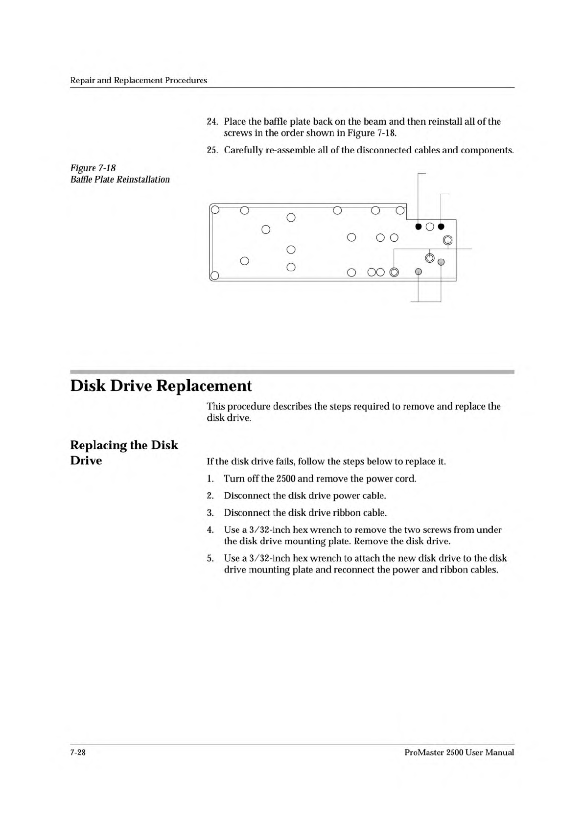
Figure
7-18
Baffle
Plate
Reinstallation
24.
Place
the
baffle
plate
back
on
the
beam
and
then
reinstall
all
of
the
screws
in
the
order
shown
in
Figure
7-18.
25.
Carefully
re-assemble
all
of
the
disconnected
cables
and
components.
Disk
Drive
Replacement
This
procedure
describes
the
steps
required
to
remove
and
replace
the
disk
drive.
Replacing
the
Disk
Drive
If
the
disk
drive
fails,
follow
the
steps
below
to
replace
it.
1.
Turn
off
the
2500
and
remove
the
power
cord.
2.
Disconnect
the
disk
drive
power
cable.
3.
Disconnect
the
disk
drive
ribbon
cable.
4.
Use
a
3/32-inch
hex
wrench
to
remove
the
two
screws
from
under
the
disk
drive
mounting
plate.
Remove
the
disk
drive.
5.
Use
a
3/32-inch
hex
wrench
to
attach
the
new
disk
drive
to
the
disk
drive
mounting
plate
and
reconnect
the
power
and
ribbon
cables.
7-28
ProMaster
2500
User
Manual
Repair
and
Replacement
Procedures
Keyboard/Display
Assembly
Replacement
This
procedure
describes
the
steps
required
to
remove
and
replace
the
keyboard
/display
assembly.
Replacing
the
Keyboard/Display
Assembly
If
the
keyboard/display
assembly
fails,
follow
the
steps
below
to
replace
it.
1.
Turn
off
the
2500
and
remove
the
power
cord.
2.
Use
the
flat
edge
of
a
flat-head
screwdriver
(or
a
table
knife)
to
pry
up
the
bottom
left
and
top
sides
of
the
keyboard/display
assembly,
which
is
affixed
with
two-sided
tape.
CAUTION:
Do
not
pry
up
the
right
side
of
the
display.
3.
Pull
the
keyboard/display
assembly
away
from
the
2500.
Note:
The
keyboard/display
assembly
is
held
in
place
with
double-sided
tape.
4.
Remove
the
two
cables
that
connect
the
keyboard/display
assembly
to
the
controller
board.
5.
Apply
double-sided
tape
to
the
underside
of
the
new
keyboard/
display
assembly.
6.
Connect
the
two
controller
board
cables
to
the
new
keyboard/display
assembly.
7.
Press
the
new
keyboard/display
assembly
into
place.
Programming
Module
Components
Replacement
These
procedures
describe
the
steps
required
to
replace
failed
components
on
programming
modules.
Replacing
Contacts
On
a
DIP
Module
Use
the
following
procedure
to
replace
the
contact
sets
on
a
programming
module.
Replace
both
sides
at
the
same
time.
1.
Mark
the
module
on
the
end
next
to
the
narrower
end
of
the
circuit
board.
You
must
reinstall
the
module
on
the
board
in
the
correct
orientation.
It
is
possible
to
reinstall
the
module
backwards
on
the
board.
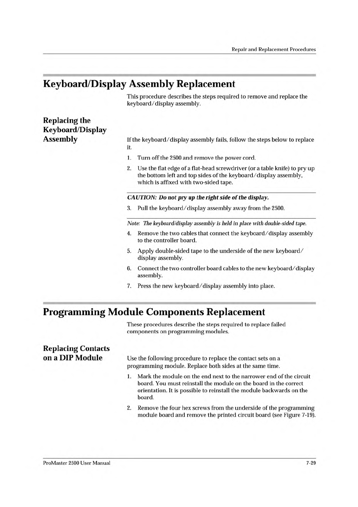
2.
Remove
the
four
hex
screws
from
the
underside
of
the
programming
module
board
and
remove
the
printed
circuit
board
(see
Figure
7-19).
ProMaster
2500
User
Manual
7-29
1927-1
PRINTED
CIRCUIT
BOARD
1928-1
SCREW
RETAINING BLOCK
CONTACT SET
Repair
and
Replacement
Procedures
Figure
7-19
Removing
the
DIP
Module
from
the
Circuit
Board
3.
Turn
the
module
so
the
underside
is
facing
you.
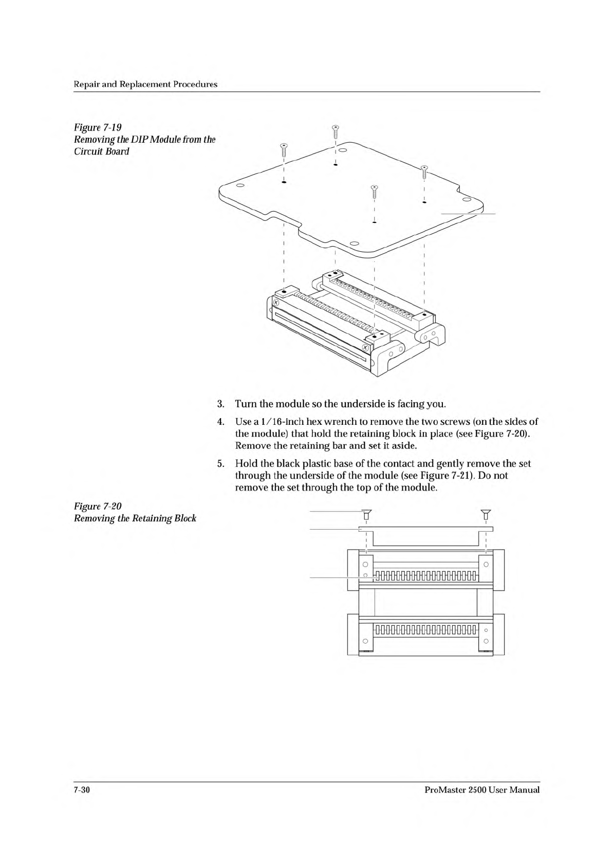
4.
Use
a
1/
16-inch
hex
wrench
to
remove
the
two
screws
(on
the
sides
of
the
module)
that
hold
the
retaining
block
in
place
(see
Figure
7-20).
Remove
the
retaining
bar
and
set
it
aside.
5.
Hold
the
black
plastic
base
of
the
contact
and
gently
remove
the
set
through
the
underside
of
the
module
(see
Figure
7-21).
Do
not
remove
the
set
through
the
top
of
the
module.
Figure
7-20
Removing
the
Retaining
Block
I
o
o
o
O
I
o
7-30
ProMaster
2500
User
Manual