2500_Users_Manual-.pdf - 第261页
Repair and Replacement Procedures 10. Test the module by running a device-related operation using the module. Replacing the Programming Block on a PLCC Module After a period of time, the protective coating on the program…
2280-2
PIN INSULATION
BLOCK
PROGRAMMING
BLOCK
CIRCUIT BOARD
FRONT
OF
HANDLER
DEVICE
Repair
and
Replacement
Procedures
The
pin
insulation
block
is
symmetrical
so
no
specific
polarity
orientation
is
required;
it
may
be
inserted
into
the
programming
block
either
way.
6.
Carefully
plug
the
programming
block
onto
the
circuit
board
using
the
block's
alignment
pins
as
guides.
The
programming
block
is
symmetrical
so
no
specific
polarity
orientation
is
required;
the
block
may
be
inserted
on
the
circuit
board
either
way.
The
block
is
seated
on
the
board
correctly
when
rests
against
the
board
on
all
sides
without
a
gap.
If
a
gap
exists,
remove
and
reseat
the
block.
7.
Turn
the
module
upside
down
and
reinsert
the
two
Phillips
screws
on
the
bottom
of
the
circuit
board.
8.
Reinsert
the
spring-loaded
module
pins
in
the
insulation
block.
Note:
One
end
of
the
module's
gold
contact
pin
is
spring-loaded
a/id
telescopes
when
pressed.
Reinsert
the
module
pin
into
the
new
insulation
block
with
the
telescoping
end
up
so
that
end
contacts
the
device
lead
during
programming.
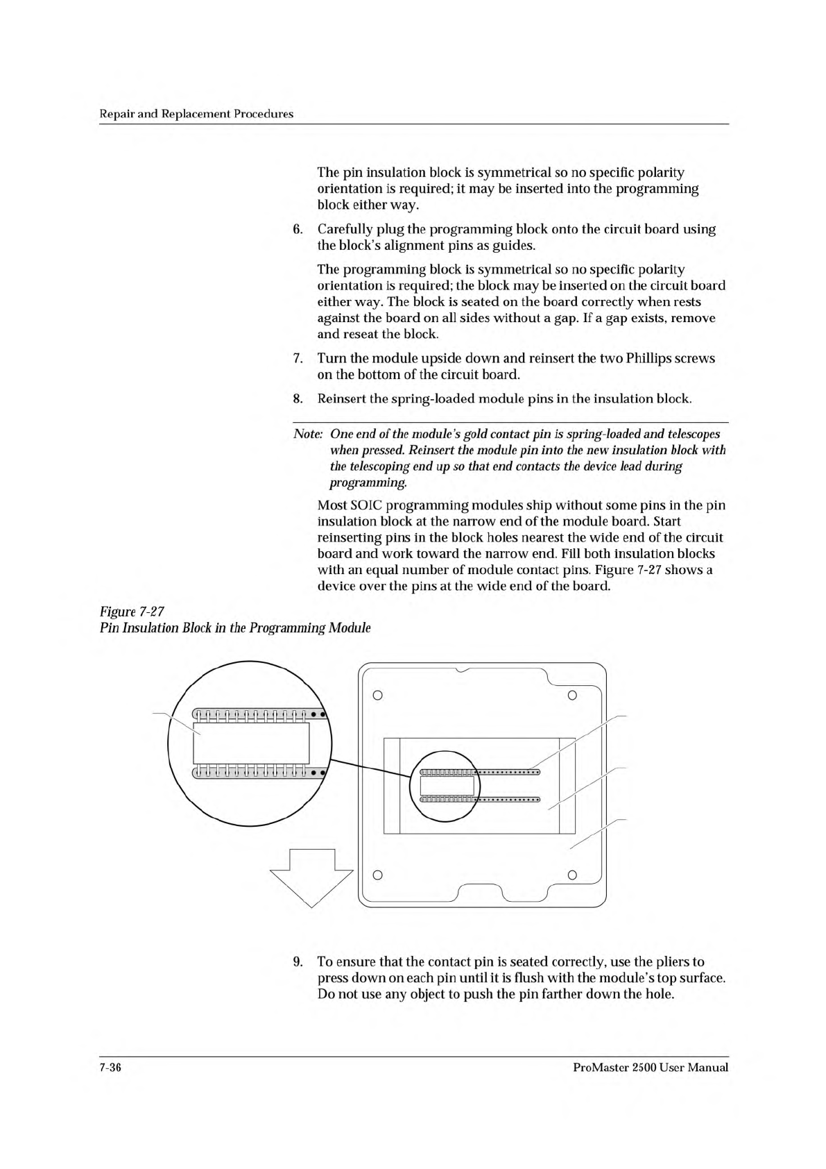
Most
SOIC
programming
modules
ship
without
some
pins
in
the
pin
insulation
block
at
the
narrow
end
of
the
module
board.
Start
reinserting
pins
in
the
block
holes
nearest
the
wide
end
of
the
circuit
board
and
work
toward
the
narrow
end.
Fill
both
insulation
blocks
with
an
equal
number
of
module
contact
pins.
Figure
7-27
shows
a
device
over
the
pins
at
the
wide
end
of
the
board.
Figure
7-27
Pin
Insulation
Block
in
the
Programming
Module
)
,
°
J
J
9.
To
ensure
that
the
contact
pin
is
seated
correctly,
use
the
pliers
to
press
down
on
each
pin
until
it
is
flush
with
the
module's
top
surface.
Do
not
use
any
object
to
push
the
pin
farther
down
the
hole.
7-36
ProMaster
2500
User
Manual
Repair
and
Replacement
Procedures
10.
Test
the
module
by
running
a
device-related
operation
using
the
module.
Replacing
the
Programming
Block
on
a
PLCC
Module
After
a
period
of
time,
the
protective
coating
on
the
programming
block
(see
Figure
7-28)
may
wear
to
the
point
that
you
begin
to
see
a
higher
number
of
device-related
errors.
If
you
have
a
second
module
of
the
same
pin
count,
you
can
confirm
that
wear
is
the
source
of
these
problems
by
programming
the
same
type
of
device
on
the
second
module
and
comparing
the
yields.
CAUTION:
To
avoid
possible
damage
to
the
system
components,
this
procedure
should
be
performed
only
by
a
qualified
service
technician.
ProMaster
2500
User
Manual
7-37
PROGRAMMING BLOCK (Top)
1667-1
DEVICE EJECTOR PIN
PROGRAMMING BLOCK (Base)
BLOCK ALIGNMENT PIN (1 of 2)
CONTACT SET
(1 of 4)
GOLD PIN
DEVICE EJECTOR SPRING
Repair
and
Replacement
Procedures
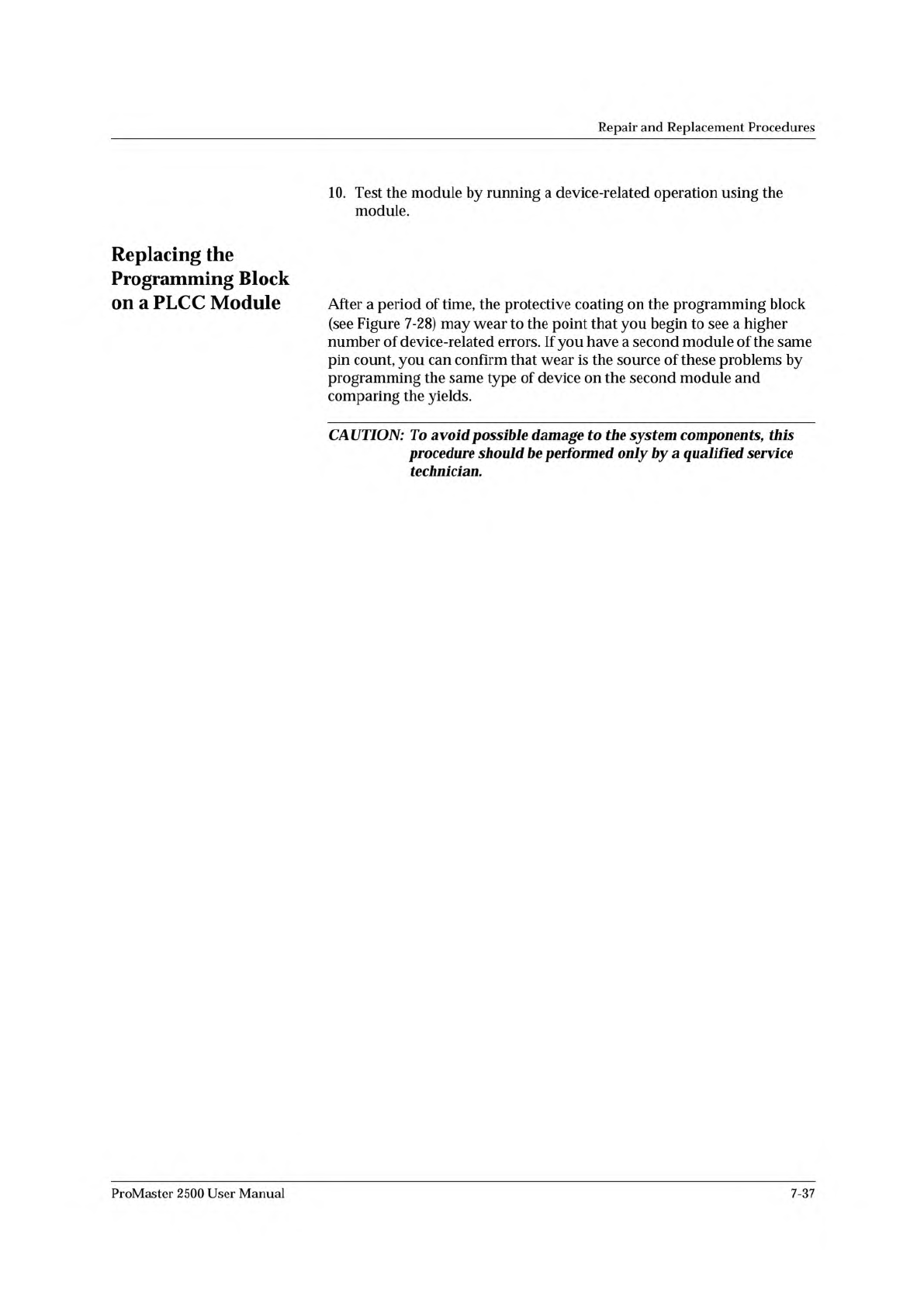
When
you
have
determined
that
the
block
needs
to
be
replaced,
follow
the
steps
listed
below.
This
procedure
describes
how
to
completely
disassemble
the
programming
module
so
you
can
replace
the
top
of
the
programming
block
(see
Figure
7-28).
Figure
7-28
PLCC
Programming
Module
(Exploded
View)
You
need
the
following
items
to
complete
this
procedure:
•
1/1
6-inch
hex
driver
•
0.050-inch
hex
driver
•
New
programming
block
(top)
CAUTION:
Remove
all
the
configuration
blocks
from
the
module
board
before
you
replace
the
programming
block.
The
pins
of
a
contact
set
might
hook
on
a
block
and
bend
or
damage
the
contacts.
7-38
ProMaster
2500
User
Manual