2500_Users_Manual-.pdf - 第30页
1770-2 LABELING STATION PRINT HEAD SPRING CLIP (1 of 2) RIBBON ADVANCE KNOB RIBBON CASSETTE PRESS BEARINGS PLATEN APPLICATION PLATE (Raised) LABEL DRIVER ROLLER PINCH ROLLER 2 PINCH ROLLER 1 LABEL ADVANCE KNOB LABEL REEL…
Introduction
Input
Tube
Holder
—
The
tube
holder
holds
a
tube
of
devices
to
be
processed
by
the
handler.
It
accepts
most
standard
IC
tubes
without
any
adjustment.
Track
Sections
—
Three
short
sections
of
track
provide
the
channel
for
devices
to
travel
through
the
system.
Devices
are
assisted
in
their
travel
down
the
track
by
the
18-degree
slope
of
the
track,
orbital
motors
that
gently
vibrate
the
devices,
and
output
track
air.
The
programming
station
stop
guide
(see
Figure
1-5)
aligns
the
device
so
that
the
beam
can
pick
it
up
and
place
it
in
the
programming
module.
Track
Width
Adjustment
Knob
—
This
knob
allows
the
user
to
adjust
the
width
of
all
three
sections
of
track
simultaneously,
allowing
quick
and
easy
changeovers
for
different
sized
devices
(see
Figure
1-5).
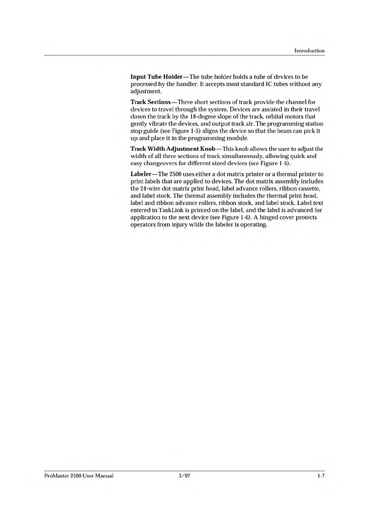
Labeler
—
The
2500
uses
either
a
dot
matrix
printer
or
a
thermal
printer
to
print
labels
that
are
applied
to
devices.
The
dot
matrix
assembly
includes
the
24-wire
dot
matrix
print
head,
label
advance
rollers,
ribbon
cassette,
and
label
stock.
The
thermal
assembly
includes
the
thermal
print
head,
label
and
ribbon
advance
rollers,
ribbon
stock,
and
label
stock.
Label
text
entered
in
TaskLink
is
printed
on
the
label,
and
the
label
is
advanced
for
application
to
the
next
device
(see
Figure
1-6).
A
hinged
cover
protects
operators
from
injury
while
the
labeler
is
operating.
ProMaster
2500
User
Manual
3/97
1-7
1770-2
LABELING STATION
PRINT HEAD
SPRING CLIP
(1 of 2)
RIBBON
ADVANCE
KNOB
RIBBON
CASSETTE
PRESS BEARINGS
PLATEN
APPLICATION PLATE (Raised)
LABEL DRIVER ROLLER
PINCH ROLLER 2
PINCH ROLLER 1
LABEL ADVANCE
KNOB
LABEL REEL COVER
LABEL
SENSING
OPTIC
ADC OPTIC (1 of 2)
Introduction
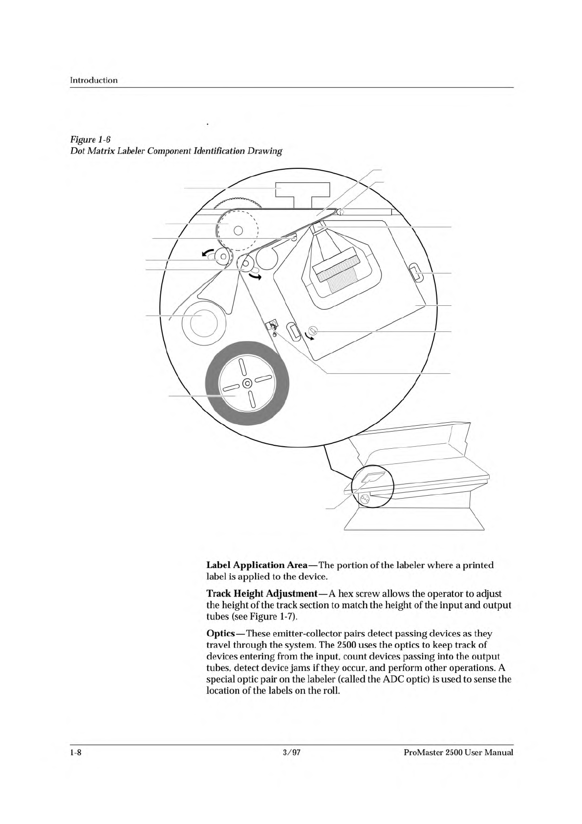
Figure
1-6
Dot
Matrix
Labeler
Component
Identification
Drawing
Label
Application
Area
—
The
portion
of
the
labeler
where
a
printed
label
is
applied
to
the
device.
Track
Height
Adjustment
—
A
hex
screw
allows
the
operator
to
adjust
the
height
of
the
track
section
to
match
the
height
of
the
input
and
output
tubes
(see
Figure
1-7).
Optics
—
These
emitter-collector
pairs
detect
passing
devices
as
they
travel
through
the
system.
The
2500
uses
the
optics
to
keep
track
of
devices
entering
from
the
input,
count
devices
passing
into
the
output
tubes,
detect
device
jams
if
they
occur,
and
perform
other
operations.
A
special
optic
pair
on
the
labeler
(called
the
ADC
optic)
is
used
to
sense
the
location
of
the
labels
on
the
roll.
1-8
3/97
ProMaster
2500
User
Manual
↵
Introduction
The
table
below
summarizes
the
keys
commonly
used
with
TaskLink
and
the
function
they
serve.
PC
Key(s)
Description
of
Action
Tab
Moves
the
cursor
to
the
next
field
(forward)
in
a
dialog
box.
Shift
+
Tab
Moves
the
cursor
to
the
previous
field
(backward)
in
a
dialog
box.
Accepts
the
current
selections
in
a
dialog
box.
In
a
multiple-line
text
entry
field,
this
key
moves
the
cursor
to
the
next
line
or
the
beginning
of
the
next
field.
Esc
Cancels
a
dialog
box
without
saving
any
changes,
or
it
cancels
any
operation
in
progress.
Arrows
Moves
the
cursor
between
selections
in
a
dialog
box.
Home,
End
Moves
the
cursor
to
the
beginning
or
end
of
a
list.
PgUp,
PgDn
Moves
the
cursor
up
one
screen
or
down
one
screen.
Fl
Accesses
context-sensitive
help.
F2
Accesses
lists
from
several
dialog
box
entry
fields.
You
are
prompted
to
press
this
key
at
appropriate
times
by
the
TaskLink
message
line
in
the
lower
left
corner
of
the
screen.
Ctrl
+
Fl
Checks
communication
between
TaskLink
and
the
Programmer
port
on
the
2500
(enter
command
from
TaskLink's
main
screen).
Ctrl
+
F2
Checks
communication
between
TaskLink
and
the
Remote
port
on
the
2500
(enter
command
from
TaskLink's
main
screen).
User
Interface
Options
Note:
Press
the
ESC
key
at
any
time
to
exit
any
menu
or
dialog
box
without
saving
and
to
display
an
Exit
TaskLink
confirmation
window.
TaskLink
Screen
—
System
operators
will
use
TaskLink
for
most
of
their
communication
with
the
system.
Most
operator
prompts
are
displayed
in
the
TaskLink
screens
on
the
PC
monitor.
Front
Panel
—
The
2500's
keyboard
and
display
will
be
used
by
the
system
operator
on
limited
occasions
to:
•
Adjust
specific
handler
parameters
using
special
function
key
commands
(refer
to
Appendix
B
for
Firmware
key
commands).
•
Align
the
beam
to
the
programming
module.
•
Read
device
handling
messages.
1-16
3/97
ProMaster
2500
User
Manual