2500_Users_Manual-.pdf - 第308页
HANDLER CONTROLLER POWER SUPPLY 7 6 5 4 3 2 1 3 2 1 P2 P1 RED YEL BLUE BLK GRN WHT BLK ORN YEL RED VIOL PROGRAMMING ELECTRONICS ASSEMBLY 1 J1 24 VOLT POWER SUPPLY TOROIDAL TRANSFORMER DISK DRIVE MOTOR POWER SUPPLY BOARD …
C
Wiring
Diagram
The
wiring
diagram
and
handler
controller
board
layout
are
included
in
this
section.
ProMaster
2500
User
Manual
C-l
HANDLER
CONTROLLER
POWER SUPPLY
7
6
5
4
3
2
1
3
2
1
P2
P1
RED
YEL
BLUE
BLK
GRN
WHT
BLK
ORN
YEL
RED
VIOL
PROGRAMMING
ELECTRONICS
ASSEMBLY
1
J1
24 VOLT
POWER SUPPLY
TOROIDAL
TRANSFORMER
DISK DRIVE
MOTOR
POWER
SUPPLY
BOARD
RED
YEL
BLUE
RED
BLK
DRIVE
FAN
RED
YEL
BLUE
1
J2
PROGRAMMING
ELECTRONICS
POWER SUPPLY
BOARD
RED
RED
BLK
BLK
NC
NC
NC
NC
8
1
BLK
WHT
GRN
6
1
AC IN
BLK
RED
RED
BLK
RED
BLK
RED
BLK
PILOT LIGHT
FAN
1
J1
1
J2
1
J3
RED
VIOL
YEL
ORN
BLK
WHT
WHT
BRN
BLK
BLUE
GRAY
J4
RED
GRN
BLUE
BLUE
BLK
BLK
GRN
WHT
BLK
BLUE
YEL
RED
NC
GRN
GRN
WHT
WHT
-24V DC
+24V DC
GND
AC (L)
AC (N)
WHT
BLK
GRN
BLUE
YEL
RED
BLK
1
WHT
WHT
GRN
GRN
J27
1
1
J2
J11
HANDLER CONTROLLER BOARD
AC
IN
CHASSIS GND
WHT
GRN
BLK
WHT
GRN
BLK
GRN
GRN
TB - 1
1
Wiring
Diagram
1 1 1 1 1 1 1 1 1 1
i
rn
rrTnl
C-2
ProMaster
2500
User
Manual
26
25
24
23
22
21
20
19
18
17
ADC
Vac
ADC
Lbl
8
7
6
5
4
3
2
1
16
15
14
13
12
11
10
9
J9
Label
J10
Rotate
J12
In-tube
J13
Out-tube
J14
Display
J6
Programmer
J7
Encoder
J15
Keyboard
J5
Remote (Prog)
J3
5V, +/-12V
J4
Remote
J1
24V
J24 Solenoids
S8 S7 S6 S5
J25 Solenoids
S4 S2 S3 S1
1.
2.
3.
4.
5.
6.
7.
8.
9.
10.
11.
12.
13.
14.
Device out of input tube
Part detect
Beam down
Beam up
(Unused)
(Unused)
(Unused)
(Unused)
(Unused)
(Unused)
Device release, track 1
Device at output tube 1
Device release, track 2
Device at output tube 2
15.
16.
17.
18.
19.
20.
21.
22.
23.
24.
25.
26.
Input track motor CAL
Output track motor CAL
Beam reference position
Out of labels detect
Input tube detect
Output tube 1 detect
Output tube 2 detect
Front prog. module clamp
Rear prog. module clamp
Hood up
Main plate up (DMP)/
End of ribbon (TP)
Unused (DMP)/
Ribbon pinch
roller open (TP)
Optic Functions
U7
82530
U37
RAM
U16
EEPROM
U15
EPROM
12V 5V
-12V
U43
8751
EPROM
J2
36V
90V
J11
Beam
U14
80C188
CPU
J8
Test
J27
Thermal Print Head
37V
90V
CR
51
CR
87
CR
63
CR
99
CR
75
CR
111
CR
52
CR
88
CR
64
CR
100
CR
76
CR
112
CR
53
CR
89
CR
65
CR
101
CR
77
CR
113
CR
54
CR
90
CR
55
CR
102
CR
78
CR
114
S1
S2
S3
S4
Unused
Output track blower (LP)
Cut off (LP)
Beam up/down (LP)
S5
S6
S7
S8
Device blow off (LP)
High pressure (HP)
Vacuum (HP)
Prog. module clamp (HP)
24V S8 S7 S6 S5 S4 S2 S3 S1
2490-1
Dot Matirix Print Head LEDs
1
1
1
1
1
1
1
1
1
1 1 1 1
1
1
1
111111
1 1
J22
Dot Matrix Print Head
J23
Dot Matrix Print Head
1
1
1
1
J15 J21 J17 J20 J16 J19
Notes
Pin 1 location for connector or IC
Dot matrix printer
Thermal printer
High pressure
Low pressure
1 =
DMP =
TP =
HP =
LP =
Refer to Figure 5-4 for specific connector pinout assignments
1
System Power
Serial Ports
Wiring
Diagram
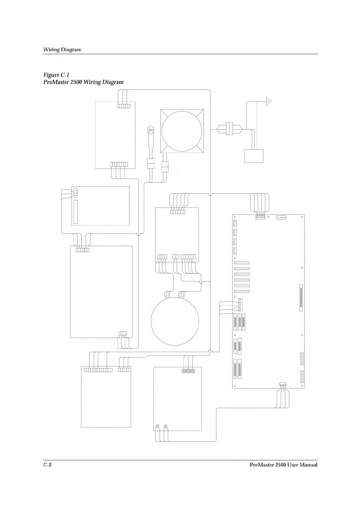
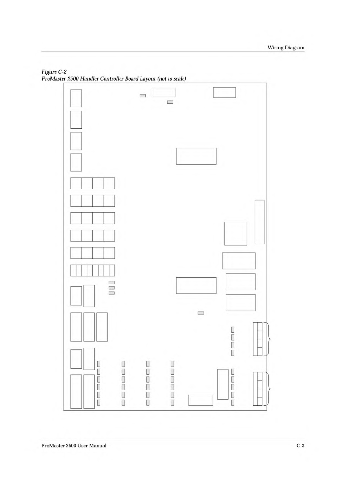
Figure
C-2
ProMaster
2500
Handler
Controller
Board
Layout
(not
to
scale)
nu
nu
nu
nu
nu
nu
nu
nu
nu
nu
nu
nu
n-
nu
nu
ProMaster
2500
User
Manual
C-3