2500_Users_Manual-.pdf - 第318页
Translation Formats The record ends with a checksum field initiated by the tag character 7 or 8, a 4-character checksum, and the tag character F. The checksum is the two's complement of the sum of the 8-bit ASCII va…
00028 7FDCFF
90000BFFFFBFFFFBFFFFBFFFFBFFFFBFFFFBFFFFBFFFF7F400F
90008BFFFFBFFFFBFFFFBFFFFBFFFFBFFFFBFFFFBFFFF7F3F8F
90010BFFFFBFFFFBFFFFBFFFFBFFFFBFFFFBFFFFBFFFF7F3FFF
90018BFFFFBFFFFBFFFFBFFFFBFFFFBFFFFBFFFFBFFFF7F3F7F
90020BFFFFBFFFFBFFFFBFFFFBFFFFBFFFFBFFFFBFFFF7F3FEF
:
Tag Character
Word Count
Tag Character
Checksum
Tag Character
Filename
End-of-File Record
Load Address
Tag Characters
Data
Records
Checksum
0429-2
LEGEND
Nonprinting Carriage Return, with optional line feed and nulls
determined by null count.
Translation
Formats
Texas
Instruments
SDSMAC
Format
(320),
Code
04
Data
files
in
the
SDSMAC
(320)
format
consist
of
a
start-of-file
record,
data
records,
and
an
end-of-file
record.
See
Figure
D-2.
The
format
is
used
for
Texas
Instruments5
320
line
of
processors.
It
is
very
similar
to
format
90;
the
only
difference
is
that
the
address
fields
represent
16-bit
data
words
rather
than
bytes
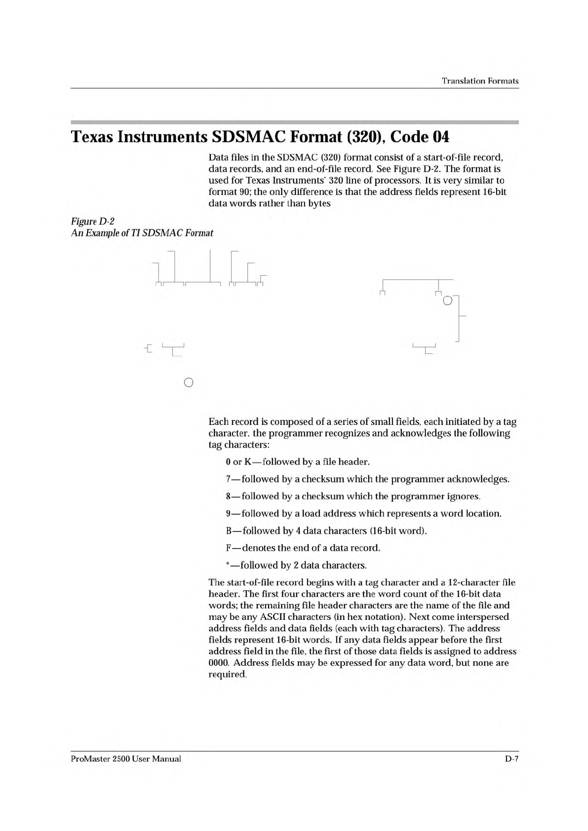
Figure
D-2
An
Example
of
TI
SDSMAC
Format
厂
nOl
o
Each
record
is
composed
of
a
series
of
small
fields,
each
initiated
by
a
tag
character,
the
programmer
recognizes
and
acknowledges
the
following
tag
characters:
0
or
K
—
followed
by
a
file
header.
7
—
followed
by
a
checksum
which
the
programmer
acknowledges.
8
—
followed
by
a
checksum
which
the
programmer
ignores.
9
—
followed
by
a
load
address
which
represents
a
word
location.
B
—
followed
by
4
data
characters
(16-bit
word).
F
—
denotes
the
end
of
a
data
record.
*
—
followed
by
2
data
characters.
The
start-of-file
record
begins
with
a
tag
character
and
a
1
2-character
file
header.
The
first
four
characters
are
the
word
count
of
the
16-bit
data
words;
the
remaining
file
header
characters
are
the
name
of
the
file
and
may
be
any
ASCII
characters
(in
hex
notation).
Next
come
interspersed
address
fields
and
data
fields
(each
with
tag
characters).
The
address
fields
represent
16-bit
words.
If
any
data
fields
appear
before
the
first
address
field
in
the
file,
the
first
of
those
data
fields
is
assigned
to
address
0000.
Address
fields
may
be
expressed
for
any
data
word,
but
none
are
required.
ProMaster
2500
User
Manual
D-7
Translation
Formats
The
record
ends
with
a
checksum
field
initiated
by
the
tag
character
7
or
8,
a
4-character
checksum,
and
the
tag
character
F.
The
checksum
is
the
two's
complement
of
the
sum
of
the
8-bit
ASCII
values
of
the
characters,
beginning
with
the
first
tag
character
and
ending
with
the
checksum
tag
character
(7
or
8).
Data
records
follow
the
same
format
as
the
start-of-file
record
but
do
not
contain
a
file
header.
The
end-of-file
record
consists
of
a
colon
(:)
only.
The
output
translator
sends
a
CTRL-S
after
the
colon.
During
download
or
input
from
disk
operations
the
destination
address
for
the
data
is
calculated
in
the
following
manner:
Memory
address
=
(load
address
x
2)
-
I/O
address
offset
+
begin
address
During
upload
or
output
to
disk
operations
the
load
address
sent
with
each
data
record
is
calculated
in
the
following
manner:
Load
address
=
I/O
address
offset
/
2
The
Memory
begin
address,
I/O
address
offset,
and
User
data
size
parameters
represent
bytes
and
must
be
even
values
for
this
format.
The
upload
record
size
must
also
be
even
for
this
format
(default
is
16).
Note:
If
the
data
will
be
programmed
into
a
1
6-bit
device
to
be
used
加
a
TMS320
processor-based
system,
the
odd/even
byte
swap
switch
must
be
enabled.
D-8
ProMaster
2500
User
Manual
Translation
Formats
The
5-Level
BNPF
Format,
Codes
08
or
09
Except
for
the
start
and
end
codes,
the
same
character
set
and
specifications
are
used
for
the
ASCII-BNPF
and
5
-level
BNPF
formats.
Data
for
input
to
the
programmer
are
punched
on
5-hole
Telex
paper
tapes
to
be
read
by
any
paper
tape
reader
that
has
an
adjustable
tape
guide.
The
reader
reads
the
tape
as
it
would
an
8-level
tape,
recording
the
5
holes
that
are
on
the
tape
as
5
bits
of
data.
The
3
most
significant
bits
are
recorded
as
if
they
were
holes
on
an
8-level
tape.
Tape
generated
from
a
telex
machine
using
this
format
can
be
input
directly
to
a
serial
paper
tape
reader
interfaced
to
the
programmer,
the
programmer's
software
converts
the
resulting
8-bit
codes
into
valid
data
for
entry
in
RAM.
The
start
code
for
the
format
is
a
left
parenthesis,
(Figs
K
on
a
telex
machine),
and
the
end
code
is
a
right
parenthesis,
(Figs
L
on
a
telex
machine).
The
5-level
BNPF
format
does
not
have
addresses.
Note:
Data
without
a
start
or
end
code
may
be
input
to
or
output
from
the
programmer
妙
use
of
the
alternate
data
translation
format
code,
09.
This
format
accepts
an
abort
character
(10
hex)
to
abort
the
transmission.
ProMaster
2500
User
Manual
D-9