2500_Users_Manual-.pdf - 第321页
RUBOUT (FF) 8 NIBBLE BYTE COUNT NULL (00) ARROW HEAD 08 6B 3E 1C 08 0483-2 DATA 00 00 00 00 04 00 00 00 Translation Formats A paper tape generated by a programmer contains a 5-byte, arrow¬ shaped header followed by a nul…
2 BYTE HEX SUMCHECK (02FB)
2 NULLS
BINARY DATA
BIT
8
BIT
1
RUBOUT (START CODE)
4 NIBBLE HEX BYTE COUNT
1 NULL
ARROW
HEAD
08
49
2A
1C
08
0
2
0
0
0020 HEX
(32 DECIMAL)
HIGH
ORDER
LOW
ORDER
0075-2
Translation
Formats
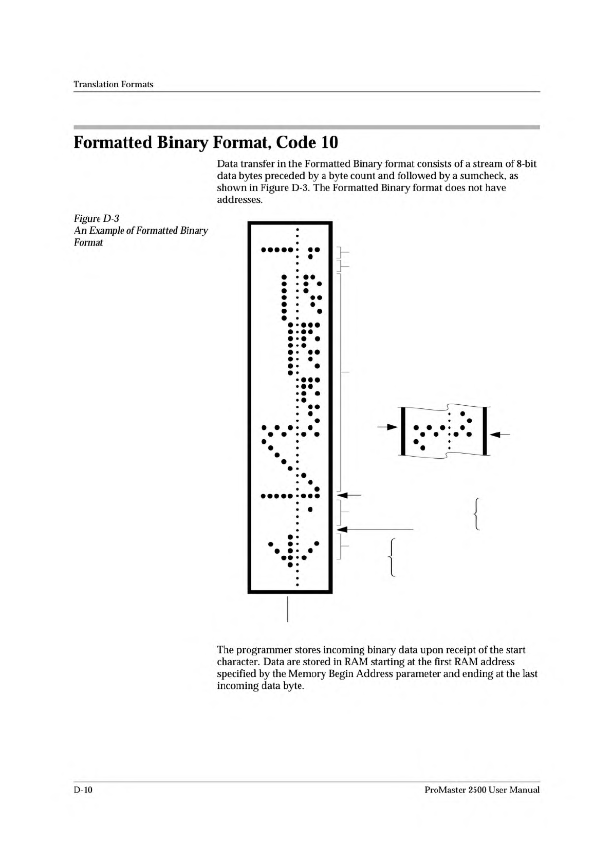
Formatted
Binary
Format,
Code
10
Data
transfer
in
the
Formatted
Binary
format
consists
of
a
stream
of
8-bit
data
bytes
preceded
by
a
byte
count
and
followed
by
a
sumcheck,
as
shown
in
Figure
D-3.
The
Formatted
Binary
format
does
not
have
addresses.
Figure
D-3
Example
of
Formatted
Binary
Format
The
programmer
stores
incoming
binary
data
upon
receipt
of
the
start
character.
Data
are
stored
in
RAM
starting
at
the
first
RAM
address
specified
by
the
Memory
Begin
Address
parameter
and
ending
at
the
last
incoming
data
byte.
D-10
ProMaster
2500
User
Manual
RUBOUT (FF)
8 NIBBLE BYTE COUNT
NULL (00)
ARROW
HEAD
08
6B
3E
1C
08
0483-2
DATA
00
00
00
00
04
00
00
00
Translation
Formats
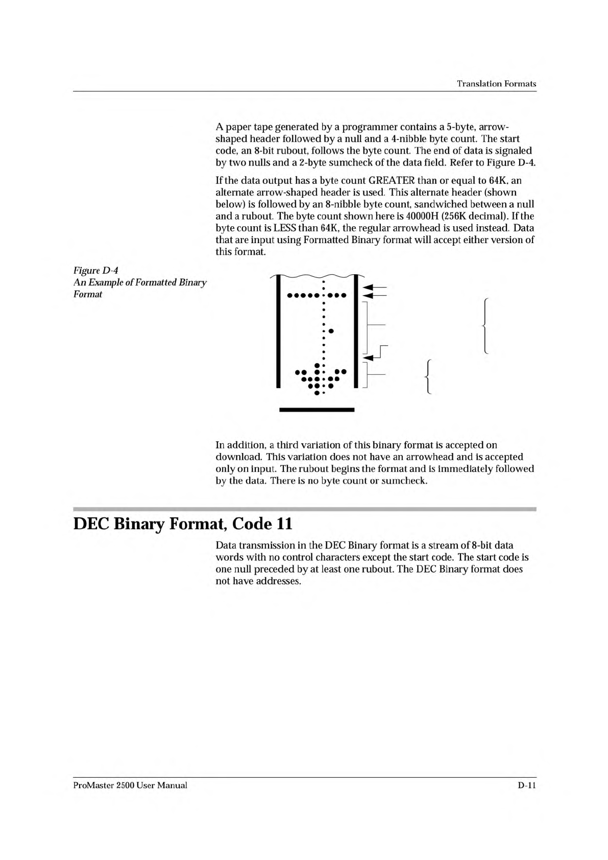
A
paper
tape
generated
by
a
programmer
contains
a
5-byte,
arrow¬
shaped
header
followed
by
a
null
and
a
4-nibble
byte
count.
The
start
code,
an
8-bit
rubout,
follows
the
byte
count.
The
end
of
data
is
signaled
by
two
nulls
and
a
2
-byte
sumcheck
of
the
data
field.
Refer
to
Figure
D-4.
If
the
data
output
has
a
byte
count
GREATER
than
or
equal
to
64K,
an
alternate
arrow-shaped
header
is
used.
This
alternate
header
(shown
below)
is
followed
by
an
8-nibble
byte
count,
sandwiched
between
a
null
and
a
rubout.
The
byte
count
shown
here
is
40000H
(256K
decimal).
If
the
byte
count
is
LESS
than
64K,
the
regular
arrowhead
is
used
instead.
Data
that
are
input
using
Formatted
Binary
format
will
accept
either
version
of
this
format.
Figure
D-4
An
Example
of
Formatted
Binary
Format
In
addition,
a
third
variation
of
this
binary
format
is
accepted
on
download.
This
variation
does
not
have
an
arrowhead
and
is
accepted
only
on
input.
The
rubout
begins
the
format
and
is
immediately
followed
by
the
data.
There
is
no
byte
count
or
sumcheck.
DEC
Binary
Format,
Code
11
Data
transmission
in
the
DEC
Binary
format
is
a
stream
of
8-bit
data
words
with
no
control
characters
except
the
start
code.
The
start
code
is
one
null
preceded
by
at
least
one
rubout.
The
DEC
Binary
format
does
not
have
addresses.
ProMaster
2500
User
Manual
D-ll
0000 11111111
0001 11111111
0002 11111111
0003 11111111
0004 11111111
0005 11111111
0006 11111111
0007 11111111
0008 11111111
0009 11111111
0010 11111111
0011 11111111
0012 11111111
0013 11111111
0014 11111111
0015 11111111
End code is a
nonprintable EXT
4 or 8 data bits appear between the
space and the carriage return
Address Code is 4
decimal digits
Optional Start Code
is a nonprintable STX
0077-2
Translation
Formats
Spectrum
Format,
Codes
12
or
13
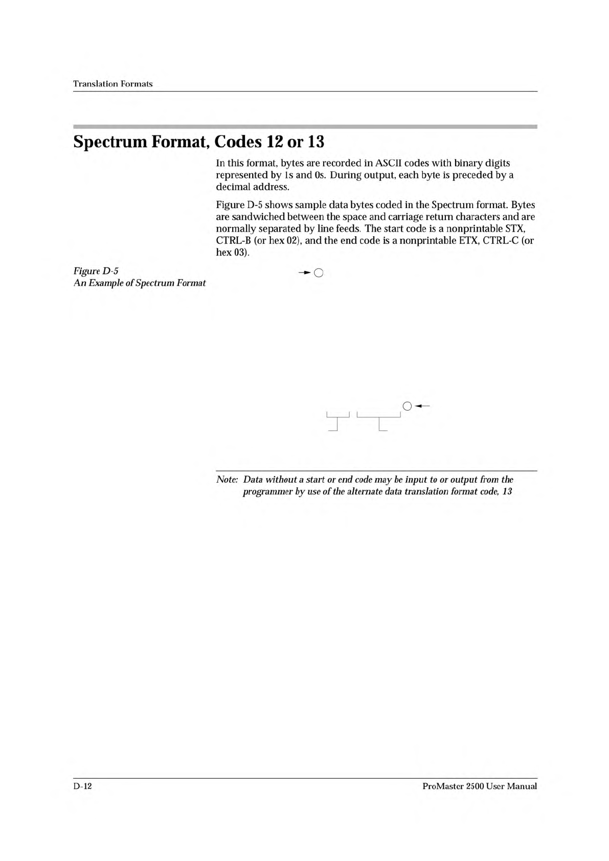
In
this
format,
bytes
are
recorded
in
ASCII
codes
with
binary
digits
represented
by
Is
and
Os.
During
output,
each
byte
is
preceded
by
a
decimal
address.
Figure
D-5
shows
sample
data
bytes
coded
in
the
Spectrum
format.
Bytes
are
sandwiched
between
the
space
and
carriage
return
characters
and
are
normally
separated
by
line
feeds.
The
start
code
is
a
nonprintable
STX,
CTRL-B
(or
hex
02),
and
the
end
code
is
a
nonprintable
ETX,
CTRL-C
(or
hex
03).
Figure
D-5
An
Example
of
Spectrum
Format
Note:
Data
without
a
start
or
end
code
may
be
input
to
or
output
from
the
programmer
by
use
of
the
alternate
data
translation
format
code,
13
D-12
ProMaster
2500
User
Manual