2500_Users_Manual-.pdf - 第369页
Translation Formats JEDEC Field Syntax <field> :: = [<delimiter>]<field identifler>{<field character〉}'*' <field identifier>::= 'A' | C | 'D' | F | 'G' |…
ABEL(tm) Version 2.00b JEDEC file for:P20R8
Large Memory Version
Created on: 09-Mar-87 04:45 PM
8-bit barrel shifter
EngineerI Data I/O Corp Redmond WA 10 Jan 1986*
QP24* QF2560*
L0000
1101111111111111111111111111101110111010
1101111111111111111111111011111110111001
1101111111111111111110111111111110110110
1101111111111111101111111111111110110101
1101111111111011111111111111111101111010
1101111110111111111111111111111101111001
1001101111111111111111111111111101110110
1001111111111111111111111111111101110101
1001111111111111111111111111101101110101
1101111111111111111111111111101110111010
1101111111111111111111111011111110111001
1101111111111111111110111111111110110110
1101111111111111101111111111111110110101
1101111111111011111111111111111101111010
1101111110111111111111111111111101111001
1001101111111111111111111111111101110110
1001111111111111111111111111111101110101
1001111111111111111111111111101101110101*
V0001 C1000000000N00HLLLLLLL1N*
V0002 C1000000000N01LHLLLLLL1N*
V0003 C1000000001N00LLHLLLLL1N*
V0004 C1000000001N01LLLHLLLL1N*
V0005 C1000000010N00LLLLHLLL1N*
V0006 C1000000010N01LLLLLHLL1N*
V0007 C1000000011N00LLLLLLHL1N*
V0008 C1000000011N01LLLLLLLH1N*
V0009 C0111111100N00LHHHHHHH1N*
V0010 C0111111100N01HLHHHHHH1N*
V0011 C0111111101N00HHLHHHHH1N*
V0012 C0111111101N01HHHLHHHH1N*
V0013 C0111111110N00HHHHLHHH1N*
V0014 C0111111110N01HHHHHLHH1N*
V0015 C0111111111N00HHHHHHLH1N*
V0016 C0111111111N01HHHHHHHL1N*
V0017 C0000000100N01HLLLLLLL1N*
V0018 C1111111000N01LHHHHHHH1N*
V0019 C0000000000N00HHHHHHHH0N*
V0020 C0000000000N10ZZZZZZZZ1N*
C1B20*
B8C0
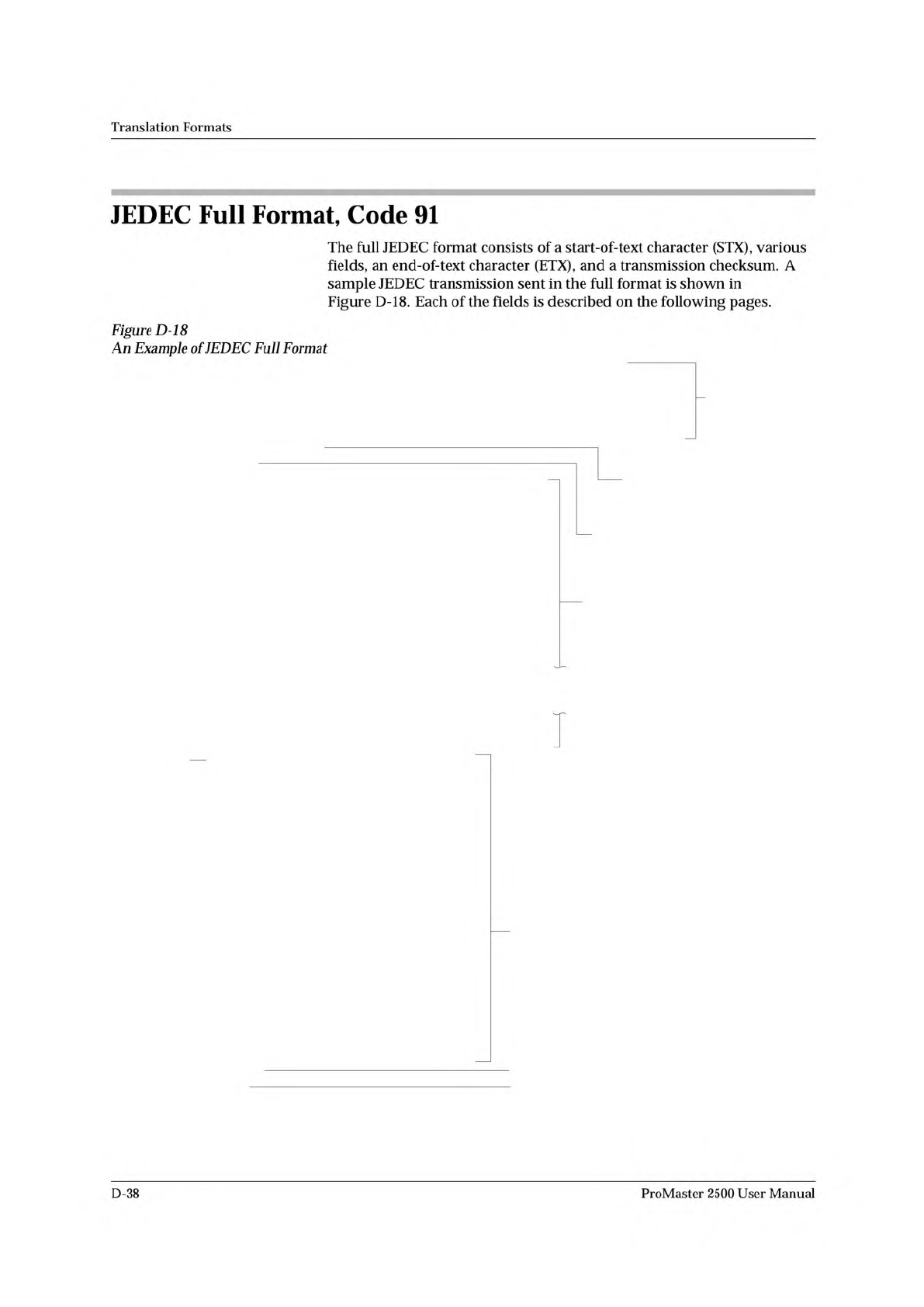
Header
(comment area -
everything
preceeding
first * is
ignored)
Number of Pins (24)
and Number of Fuses (2560)
Fuse Address (0000)
Fuse States:
0 = intact
1 = blown
Test Vectors
Fuse Map Checksum
Transmission Checksum
0090-3
Vector
Number
Translation
Formats
JEDEC
Full
Format,
Code
91
The
full
JEDEC
format
consists
of
a
start-of-text
character
(STX),
various
fields,
an
end-of-text
character
(ETX),
and
a
transmission
checksum.
A
sample
JEDEC
transmission
sent
in
the
full
format
is
shown
in
Figure
D-18.
Each
of
the
fields
is
described
on
the
following
pages.
Figure
D-18
An
Example
of
JEDEC
Full
Format
D-38
ProMaster
2500
User
Manual
Translation
Formats
JEDEC
Field
Syntax
<field>
::
=
[<delimiter>]<field
identifler>{<field
character〉}'*'
<field
identifier>::=
'A'
|
C
|
'D'
|
F
|
'G'
|
K
|
'L'
|
'N'
|
P
|
qTrTstttvtx,
〈
reserved
identifier>::=
'B'
|
E
|
'H'
|
T
|
'J'
|
'M'
「
0'
|
'U'
|
'W'
1
,y,
।
Z
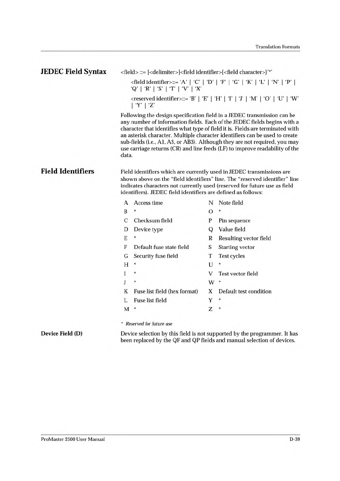
Following
the
design
specification
field
in
a
JEDEC
transmission
can
be
any
number
of
information
fields.
Each
of
the
JEDEC
fields
begins
with
a
character
that
identifies
what
type
of
field
it
is.
Fields
are
terminated
with
an
asterisk
character.
Multiple
character
identifiers
can
be
used
to
create
sub-fields
(i.e.,
Al,
A$,
or
AB3).
Although
they
are
not
required,
you
may
use
carriage
returns
(CR)
and
line
feeds
(LF)
to
improve
readability
of
the
data.
Field
Identifiers
Field
identifiers
which
are
currently
used
in
JEDEC
transmissions
are
shown
above
on
the
“field
identifiers
n
line.
The
“reserved
identifier
M
line
indicates
characters
not
currently
used
(reserved
for
future
use
as
field
identifiers).
JEDEC
field
identifiers
are
defined
as
follows:
A
Access
time
N
Note
field
B
*
O
*
C
Checksum
field
P
Pin
sequence
D
Device
type
Q
Value
field
E
*
R
Resulting
vector
field
F
Default
fuse
state
field
S
Starting
vector
G
Security
fuse
field
T
Test
cycles
H
*
U
*
I
*
V
Test
vector
field
J
*
w
*
K
Fuse
list
field
(hex
format)
X
Default
test
condition
L
Fuse
list
field
Y
*
M
*
Z
*
Device
Field
(D)
*
Reserved
for
future
use
Device
selection
by
this
field
is
not
supported
by
the
programmer.
It
has
been
replaced
by
the
QF
and
QP
fields
and
manual
selection
of
devices.
ProMaster
2500
User
Manual
D-39
Translation
Formats
Fuse
Information
Fields
(L,
K,
F,
C)
<fuse
information〉
::
=
[<default
state>]
<fuse
list>
{<fuse
list>}
[<fuse
checksum
>]
<fuse
list〉
:
=
,L'
<number>
<delimiter>
{<binary-digit>
[<delimiter>]}
•
*
t
<fuse
list〉
::
=
,K'
<number>
<
delimiter
>
{<
hex-digit
>
[vdelimiter〉]}
'*,
<
default
state>
::
=
'F'
〈
binary-digit〉
'
vfuse
checksum〉
::
=
'C'
<hex-digit>:4
'*
'
Each
fuse
of
a
device
is
assigned
a
decimal
number
and
has
two
possible
states:
zero,
specifying
a
low-resistance
link,
or
one,
specifying
a
high
resistance
link.
The
state
of
each
fuse
in
the
device
is
given
by
three
fields:
the
fuse
list
(L
field
or
K
field),
the
default
state
(F
field),
and
the
fuse
checksum
(C
field).
Fuse
states
are
explicitly
defined
by
either
the
L
field
or
the
K
field.
The
character
L
begins
the
L
field
and
is
followed
by
the
decimal
number
of
the
first
fuse
for
which
this
field
defines
a
state.
The
first
fuse
number
is
followed
by
a
list
of
binary
values
indicating
the
fuse
states.
The
information
in
the
K
field
is
the
same
as
that
of
the
L
field
except
that
the
information
is
represented
by
hex
characters
instead
of
binary
values.
This
allows
more
compact
representation
of
the
fusemap
data.
The
character
K
begins
the
K
field
and
is
followed
by
the
decimal
number
of
the
first
fuse.
The
fuse
data
follow
the
fuse
number
and
are
represented
by
hex
characters.
Each
bit
of
each
hex
character
represents
the
state
of
one
fuse,
so
each
hex
character
represents
four
fuses.
The
most
significant
bit
of
the
first
hex
character
following
the
fuse
number
corresponds
to
the
state
of
that
fuse
number.
The
next
most
significant
bit
corresponds
to
the
state
of
the
next
fuse
number,
etc.
The
least
significant
bit
of
the
first
hex
character
corresponds
to
the
state
of
the
fuse
at
the
location
specified
by
the
fuse
number
plus
three.
The
K
field
supports
download
operations
only.
The
K
field
is
not
part
of
the
JEDEC
standard,
but
is
supported
by
Data
I/O
for
fast
data
transfer.
The
L
and
K
fields
can
be
any
length
desired,
and
any
number
of
L
or
K
fields
can
be
specified.
If
the
state
of
a
fuse
is
specified
more
than
once,
the
last
state
specified
replaces
all
previous
ones
for
that
fuse.
The
F
field
defines
the
states
of
fuses
that
are
not
explicitly
defined
in
the
L
or
K
fields.
If
no
F
field
is
specified,
all
fuse
states
must
be
defined
by
L
or
K
fields.
D-40
ProMaster
2500
User
Manual