2500_Users_Manual-.pdf - 第370页
Translation Formats Fuse Information Fields (L, K, F, C) <fuse information〉 :: = [<default state>] <fuse list> {<fuse list>} [<fuse checksum >] <fuse list〉 : = ,L' <number> <de…
Translation
Formats
JEDEC
Field
Syntax
<field>
::
=
[<delimiter>]<field
identifler>{<field
character〉}'*'
<field
identifier>::=
'A'
|
C
|
'D'
|
F
|
'G'
|
K
|
'L'
|
'N'
|
P
|
qTrTstttvtx,
〈
reserved
identifier>::=
'B'
|
E
|
'H'
|
T
|
'J'
|
'M'
「
0'
|
'U'
|
'W'
1
,y,
।
Z
Following
the
design
specification
field
in
a
JEDEC
transmission
can
be
any
number
of
information
fields.
Each
of
the
JEDEC
fields
begins
with
a
character
that
identifies
what
type
of
field
it
is.
Fields
are
terminated
with
an
asterisk
character.
Multiple
character
identifiers
can
be
used
to
create
sub-fields
(i.e.,
Al,
A$,
or
AB3).
Although
they
are
not
required,
you
may
use
carriage
returns
(CR)
and
line
feeds
(LF)
to
improve
readability
of
the
data.
Field
Identifiers
Field
identifiers
which
are
currently
used
in
JEDEC
transmissions
are
shown
above
on
the
“field
identifiers
n
line.
The
“reserved
identifier
M
line
indicates
characters
not
currently
used
(reserved
for
future
use
as
field
identifiers).
JEDEC
field
identifiers
are
defined
as
follows:
A
Access
time
N
Note
field
B
*
O
*
C
Checksum
field
P
Pin
sequence
D
Device
type
Q
Value
field
E
*
R
Resulting
vector
field
F
Default
fuse
state
field
S
Starting
vector
G
Security
fuse
field
T
Test
cycles
H
*
U
*
I
*
V
Test
vector
field
J
*
w
*
K
Fuse
list
field
(hex
format)
X
Default
test
condition
L
Fuse
list
field
Y
*
M
*
Z
*
Device
Field
(D)
*
Reserved
for
future
use
Device
selection
by
this
field
is
not
supported
by
the
programmer.
It
has
been
replaced
by
the
QF
and
QP
fields
and
manual
selection
of
devices.
ProMaster
2500
User
Manual
D-39
Translation
Formats
Fuse
Information
Fields
(L,
K,
F,
C)
<fuse
information〉
::
=
[<default
state>]
<fuse
list>
{<fuse
list>}
[<fuse
checksum
>]
<fuse
list〉
:
=
,L'
<number>
<delimiter>
{<binary-digit>
[<delimiter>]}
•
*
t
<fuse
list〉
::
=
,K'
<number>
<
delimiter
>
{<
hex-digit
>
[vdelimiter〉]}
'*,
<
default
state>
::
=
'F'
〈
binary-digit〉
'
vfuse
checksum〉
::
=
'C'
<hex-digit>:4
'*
'
Each
fuse
of
a
device
is
assigned
a
decimal
number
and
has
two
possible
states:
zero,
specifying
a
low-resistance
link,
or
one,
specifying
a
high
resistance
link.
The
state
of
each
fuse
in
the
device
is
given
by
three
fields:
the
fuse
list
(L
field
or
K
field),
the
default
state
(F
field),
and
the
fuse
checksum
(C
field).
Fuse
states
are
explicitly
defined
by
either
the
L
field
or
the
K
field.
The
character
L
begins
the
L
field
and
is
followed
by
the
decimal
number
of
the
first
fuse
for
which
this
field
defines
a
state.
The
first
fuse
number
is
followed
by
a
list
of
binary
values
indicating
the
fuse
states.
The
information
in
the
K
field
is
the
same
as
that
of
the
L
field
except
that
the
information
is
represented
by
hex
characters
instead
of
binary
values.
This
allows
more
compact
representation
of
the
fusemap
data.
The
character
K
begins
the
K
field
and
is
followed
by
the
decimal
number
of
the
first
fuse.
The
fuse
data
follow
the
fuse
number
and
are
represented
by
hex
characters.
Each
bit
of
each
hex
character
represents
the
state
of
one
fuse,
so
each
hex
character
represents
four
fuses.
The
most
significant
bit
of
the
first
hex
character
following
the
fuse
number
corresponds
to
the
state
of
that
fuse
number.
The
next
most
significant
bit
corresponds
to
the
state
of
the
next
fuse
number,
etc.
The
least
significant
bit
of
the
first
hex
character
corresponds
to
the
state
of
the
fuse
at
the
location
specified
by
the
fuse
number
plus
three.
The
K
field
supports
download
operations
only.
The
K
field
is
not
part
of
the
JEDEC
standard,
but
is
supported
by
Data
I/O
for
fast
data
transfer.
The
L
and
K
fields
can
be
any
length
desired,
and
any
number
of
L
or
K
fields
can
be
specified.
If
the
state
of
a
fuse
is
specified
more
than
once,
the
last
state
specified
replaces
all
previous
ones
for
that
fuse.
The
F
field
defines
the
states
of
fuses
that
are
not
explicitly
defined
in
the
L
or
K
fields.
If
no
F
field
is
specified,
all
fuse
states
must
be
defined
by
L
or
K
fields.
D-40
ProMaster
2500
User
Manual
F0*L0 01010101* L0008 01010111* L1000 0101*C019E*
F0*K0 55* K0008 57* K1000 5* C019E*
L0200 01101010101010101011
010111010110100010010010010*
G1
Translation
Formats
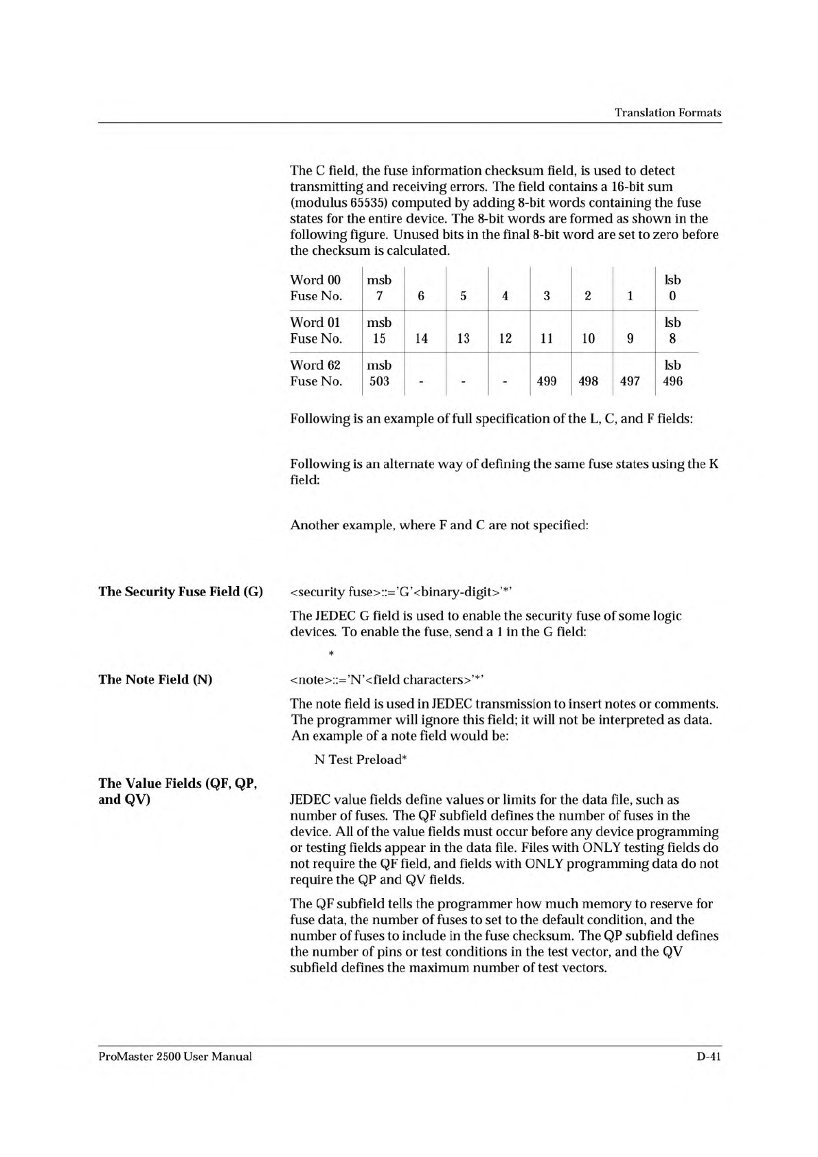
The
C
field,
the
fuse
information
checksum
field,
is
used
to
detect
transmitting
and
receiving
errors.
The
field
contains
a
16-bit
sum
(modulus
65535)
computed
by
adding
8-bit
words
containing
the
fuse
states
for
the
entire
device.
The
8-bit
words
are
formed
as
shown
in
the
following
figure.
Unused
bits
in
the
final
8-bit
word
are
set
to
zero
before
the
checksum
is
calculated.
Word
00
Fuse
No.
msb
7
6
5
4
3
2
1
Isb
0
Word
01
Fuse
No.
msb
15
14
13
12
11
10
9
Isb
8
Word
62
Fuse
No.
msb
503
- - -
499
498
497
Isb
496
Following
is
an
example
of
full
specification
of
the
L,
C,
and
F
fields:
Following
is
an
alternate
way
of
defining
the
same
fuse
states
using
the
K
field:
Another
example,
where
F
and
C
are
not
specified:
The
Security
Fuse
Field
(G)
〈
security
fuse
>
'
G
'
v
binary-digit
>
'
*
'
The
JEDEC
G
field
is
used
to
enable
the
security
fuse
of
some
logic
devices.
To
enable
the
fuse,
send
a
1
in
the
G
field:
*
The
Note
Field
(N)
<note>::=,N,<field
characters〉'*'
The
note
field
is
used
in
JEDEC
transmission
to
insert
notes
or
comments.
The
programmer
will
ignore
this
field;
it
will
not
be
interpreted
as
data.
An
example
of
a
note
field
would
be:
N
Test
Preload*
The
Value
Fields
(QF,
QP,
and
QV)
JEDEC
value
fields
define
values
or
limits
for
the
data
file,
such
as
number
of
fuses.
The
QF
subfield
defines
the
number
of
fuses
in
the
device.
All
of
the
value
fields
must
occur
before
any
device
programming
or
testing
fields
appear
in
the
data
file.
Files
with
ONLY
testing
fields
do
not
require
the
QF
field,
and
fields
with
ONLY
programming
data
do
not
require
the
QP
and
QV
fields.
The
QF
subfield
tells
the
programmer
how
much
memory
to
reserve
for
fuse
data,
the
number
of
fuses
to
set
to
the
default
condition,
and
the
number
of
fuses
to
include
in
the
fuse
checksum.
The
QP
subfield
defines
the
number
of
pins
or
test
conditions
in
the
test
vector,
and
the
QV
subfield
defines
the
maximum
number
of
test
vectors.
ProMaster
2500
User
Manual
D-41