2500_Users_Manual-.pdf - 第373页
<User Data Fuse List>: : ’ U ’ <binary-digit(s)> ’ * ’ QF24* L0000 1010110000000000000000 00* E10100111* C011A* U10110110* <Electrical Data Fuse List>:: ’ E ’ <binary digit(s)> ’ * ’ QF24* L0000 1…
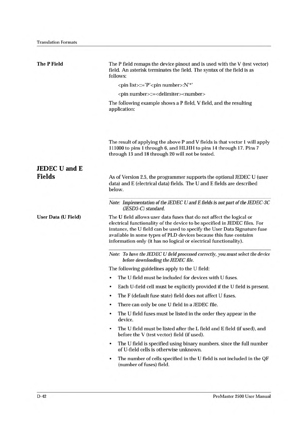
P 1 2 3 4 5 6 14 15 16 17 7 8 9 10 11 12 13 18 19 20 *
V0001 111000HLHHNNNNNNNNNN*
V0002 100000HHHLNNNNNNNNNN*
Translation
Formats
The
P
Field
The
P
field
remaps
the
device
pinout
and
is
used
with
the
V
(test
vector)
field.
An
asterisk
terminates
the
field.
The
syntax
of
the
field
is
as
follows:
<pin
Hst>::='P'vpin
number>:N^*^
<pin
number>::=<delimiterxnumber>
The
following
example
shows
a
P
field,
V
field,
and
the
resulting
application:
The
result
of
applying
the
above
P
and
V
fields
is
that
vector
1
will
apply
111000
to
pins
1
through
6,
and
HLHH
to
pins
14
through
17.
Pins
7
through
13
and
18
through
20
will
not
be
tested.
JEDEC
U
and
E
Fields
As
of
Version
2.5,
the
programmer
supports
the
optional
JEDEC
U
(user
data)
and
E
(electrical
data)
fields.
The
U
and
E
fields
are
described
below.
Note:
Implementation
of
the
JEDEC
U
and
E
fields
is
not
part
of
the
JEDEC-
3c
(JESD3-C)
standard.
User
Data
(U
Field)
The
U
field
allows
user
data
fuses
that
do
not
affect
the
logical
or
electrical
functionality
of
the
device
to
be
specified
in
JEDEC
files.
For
instance,
the
U
field
can
be
used
to
specify
the
User
Data
Signature
fuse
available
in
some
types
of
PLD
devices
because
this
fuse
contains
information
only
(it
has
no
logical
or
electrical
functionality).
Note:
To
have
the
JEDEC
U
field
processed
correctly,
you
must
select
the
device
before
downloading
the
JEDEC
6/e.
The
following
guidelines
apply
to
the
U
field:
•
The
U
field
must
be
included
for
devices
with
U
fuses.
•
Each
U-field
cell
must
be
explicitly
provided
if
the
U
field
is
present.
•
The
F
(default
fuse
state)
field
does
not
affect
U
fuses.
•
There
can
only
be
one
U
field
in
a
JEDEC
file.
•
The
U
field
fuses
must
be
listed
in
the
order
they
appear
in
the
device.
•
The
U
field
must
be
listed
after
the
L
field
and
E
field
(if
used),
and
before
the
V
(test
vector)
field
(if
used).
•
The
U
field
is
specified
using
binary
numbers,
since
the
full
number
of
U-field
cells
is
otherwise
unknown.
•
The
number
of
cells
specified
in
the
U
field
is
not
included
in
the
QF
(number
of
fuses)
field.
D-42
ProMaster
2500
User
Manual
<User Data Fuse List>::’U’<binary-digit(s)>’*’
QF24*
L0000
101011000000000000000000*
E10100111*
C011A*
U10110110*
<Electrical Data Fuse List>::’E’<binary digit(s)>’*’
QF24*
L0000
101011000000000000000000*
E10100111*
C011A*
U10110110*
Translation
Formats
Electrical
Data
(E
field)
•
The
U-field
cells
are
not
included
in
the
C
(fuse
checksum)
field.
•
The
U
field
reads
left
to
right
to
be
consistent
with
the
L
(fuse
list)
and
E
fields.
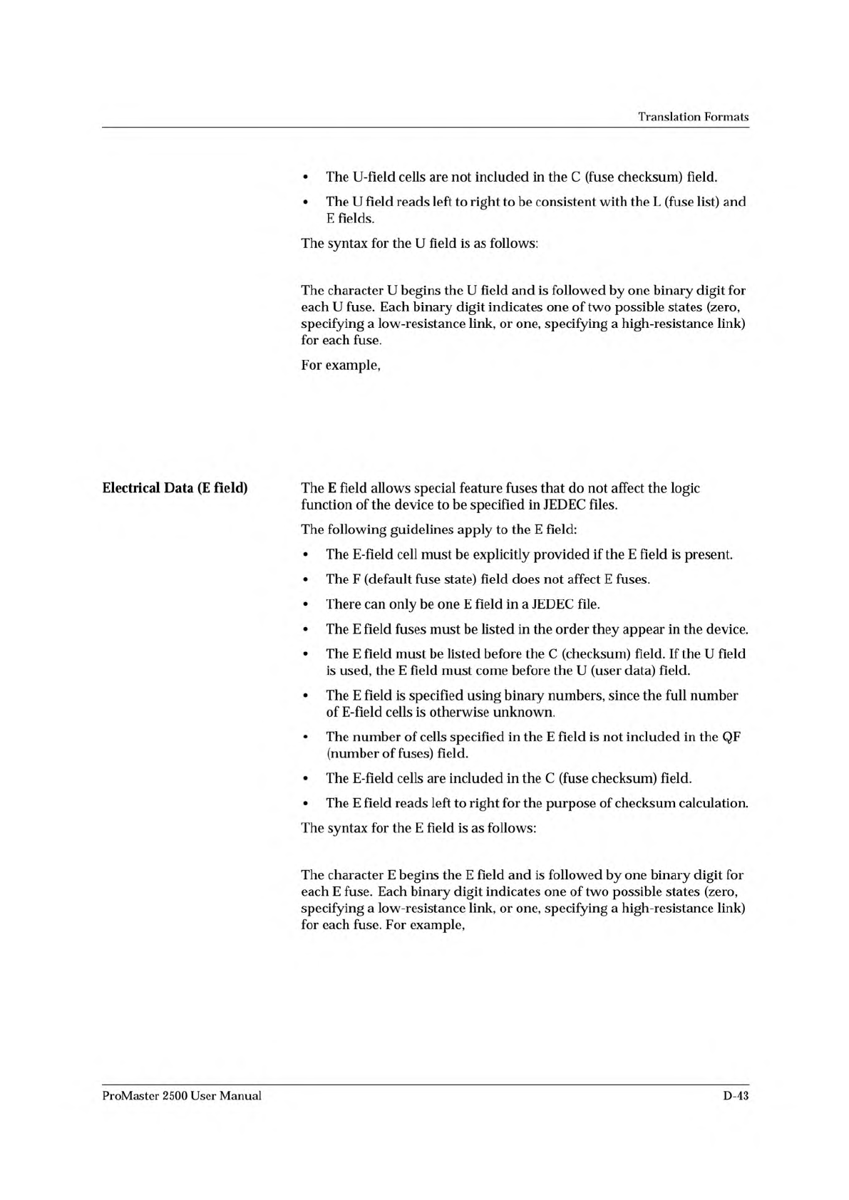
The
syntax
for
the
U
field
is
as
follows:
The
character
U
begins
the
U
field
and
is
followed
by
one
binary
digit
for
each
U
fuse.
Each
binary
digit
indicates
one
of
two
possible
states
(zero,
specifying
a
low-resistance
link,
or
one,
specifying
a
high-resistance
link)
for
each
fuse.
For
example,
The
E
field
allows
special
feature
fuses
that
do
not
affect
the
logic
function
of
the
device
to
be
specified
in
JEDEC
files.
The
following
guidelines
apply
to
the
E
field:
•
The
E-field
cell
must
be
explicitly
provided
if
the
E
field
is
present.
•
The
F
(default
fuse
state)
field
does
not
affect
E
fuses.
•
There
can
only
be
one
E
field
in
a
JEDEC
file.
•
The
E
field
fuses
must
be
listed
in
the
order
they
appear
in
the
device.
•
The
E
field
must
be
listed
before
the
C
(checksum)
field.
If
the
U
field
is
used,
the
E
field
must
come
before
the
U
(user
data)
field.
•
The
E
field
is
specified
using
binary
numbers,
since
the
full
number
of
E-field
cells
is
otherwise
unknown.
•
The
number
of
cells
specified
in
the
E
field
is
not
included
in
the
QF
(number
of
fuses)
field.
•
The
E-field
cells
are
included
in
the
C
(fuse
checksum)
field.
•
The
E
field
reads
left
to
right
for
the
purpose
of
checksum
calculation.
The
syntax
for
the
E
field
is
as
follows:
The
character
E
begins
the
E
field
and
is
followed
by
one
binary
digit
for
each
E
fuse.
Each
binary
digit
indicates
one
of
two
possible
states
(zero,
specifying
a
low-resistance
link,
or
one,
specifying
a
high-resistance
link)
for
each
fuse.
For
example,
ProMaster
2500
User
Manual
D-43
Translation
Formats
Test
Field
(V
field)
<
function
test>
::
=
[<pin
list〉]
<test
vector>
{<test
vector>}
<pin
number>
::
=
<
delimiter
>
<number>
N
::
=
number
of
pins
on
device
<test
vector>
::
=
'V'
<number>
<delimiter>
<
test
condition〉
:
N
vtest
condition〉
=
vdigit>
B
「CTDTFTHTKTLTN」P
|u「xtz,
〈
reserved
condition〉
::
=
'A'
|
E
|
'G'
|
T
|
'J'
|
'M'
|
'0'
|
Q
|
'R'
|
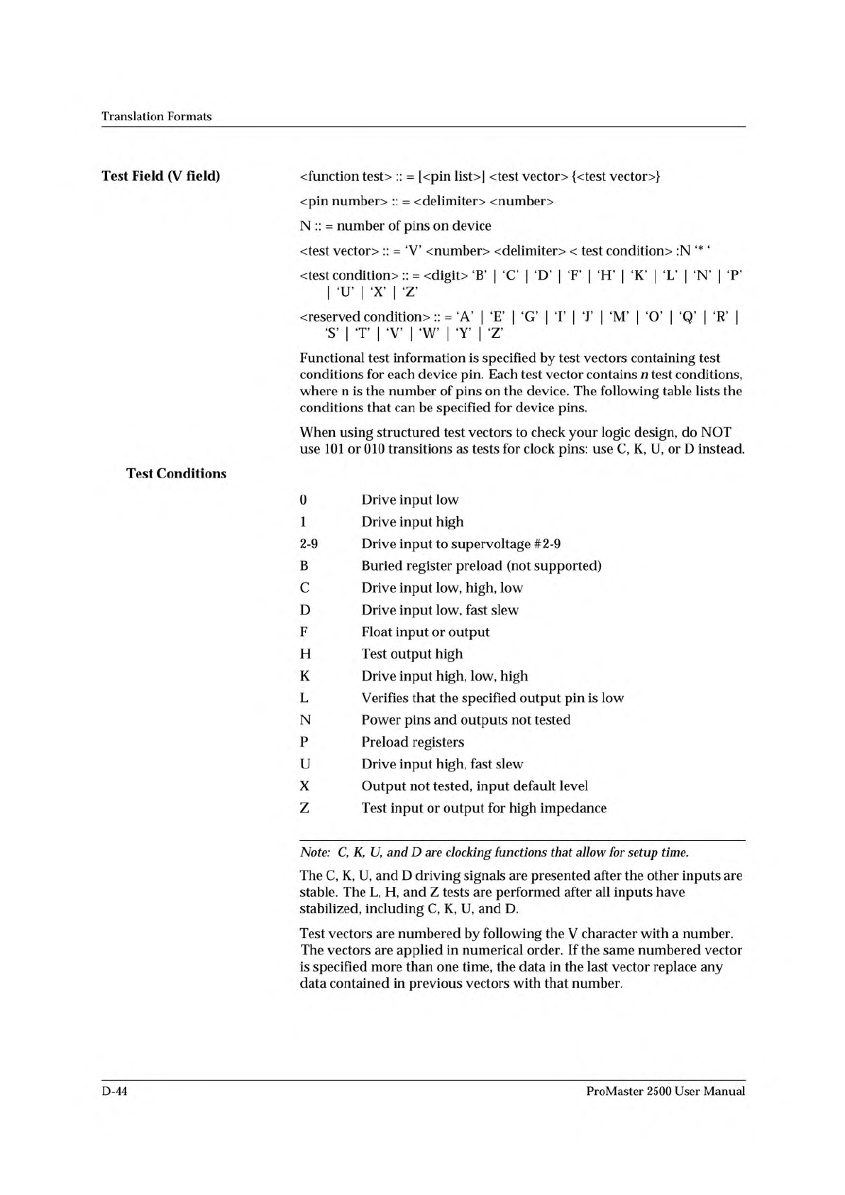
Functional
test
information
is
specified
by
test
vectors
containing
test
conditions
for
each
device
pin.
Each
test
vector
contains
n
test
conditions,
where
n
is
the
number
of
pins
on
the
device.
The
following
table
lists
the
conditions
that
can
be
specified
for
device
pins.
When
using
structured
test
vectors
to
check
your
logic
design,
do
NOT
use
101
or
010
transitions
as
tests
for
clock
pins:
use
C,
K,
U,
or
D
instead.
Test
Conditions
Drive
input
low
Drive
input
high
Drive
input
to
supervoltage
#2-9
Buried
register
preload
(not
supported)
Drive
input
low,
high,
low
Drive
input
low,
fast
slew
Float
input
or
output
Test
output
high
Drive
input
high,
low,
high
Verifies
that
the
specified
output
pin
is
low
Power
pins
and
outputs
not
tested
Preload
registers
Drive
input
high,
fast
slew
Output
not
tested,
input
default
level
Test
input
or
output
for
high
impedance
0
1
2-9
B
C
D
F
H
L
N
P
U
X
z
Note:
C,
K,
U,
and
D
are
clocking
functions
that
allow
for
setup
time.
The
C,
K,
U,
and
D
driving
signals
are
presented
after
the
other
inputs
are
stable.
The
L,
H,
and
Z
tests
are
performed
after
all
inputs
have
stabilized,
including
C,
K,
U,
and
D.
Test
vectors
are
numbered
by
following
the
V
character
with
a
number.
The
vectors
are
applied
in
numerical
order.
If
the
same
numbered
vector
is
specified
more
than
one
time,
the
data
in
the
last
vector
replace
any
data
contained
in
previous
vectors
with
that
number.
D-44
ProMaster
2500
User
Manual