2500_Users_Manual-.pdf - 第38页
2306-1 FRONT REAR TOP PALET Installation and Setup Figure 2-2 The 2500 Shipping Crate 1. Remove the eight screws (two on each vertical panel) that hold together the panels of the shipping crate (see Figure 2-2). 2. Caref…
↵
•
Introduction
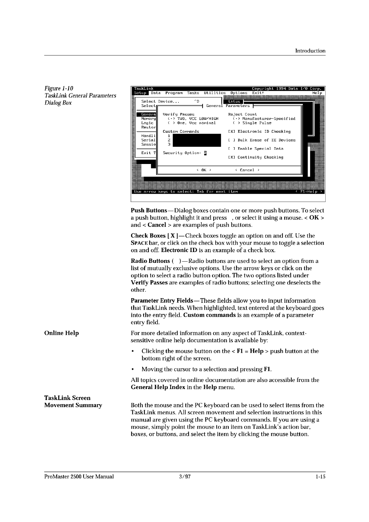
Figure
I
-10
TaskLink
General
Parameters
Dialog
Box
Online
Help
TaskLink
Screen
Movement
Summaiy
Push
Buttons
—
Dialog
boxes
contain
one
or
more
push
buttons.
To
select
a
push
button,
highlight
it
and
press
,
or
select
it
using
a
mouse.
<
OK
>
and
<
Cancel
>
are
examples
of
push
buttons.
Check
Boxes
[
X
]
—
Check
boxes
toggle
an
option
on
and
off.
Use
the
Space
bar,
or
click
on
the
check
box
with
your
mouse
to
toggle
a
selection
on
and
off.
Electronic
ID
is
an
example
of
a
check
box.
Radio
Buttons
(
)
—
Radio
buttons
are
used
to
select
an
option
from
a
list
of
mutually
exclusive
options.
Use
the
arrow
keys
or
click
on
the
option
to
select
a
radio
button
option.
The
two
options
listed
under
Verify
Passes
are
examples
of
radio
buttons;
selecting
one
deselects
the
other.
Parameter
Entry
Fields
—
These
fields
allow
you
to
input
information
that
TaskLink
needs.
When
highlighted,
text
entered
at
the
keyboard
goes
into
the
entry
field.
Custom
commands
is
an
example
of
a
parameter
entry
field.
For
more
detailed
information
on
any
aspect
of
TaskLink,
context-
sensitive
online
help
documentation
is
available
by:
•
Clicking
the
mouse
button
on
the
<
Fl
=
Help
>
push
button
at
the
bottom
right
of
the
screen.
•
Moving
the
cursor
to
a
selection
and
pressing
Fl.
All
topics
covered
in
online
documentation
are
also
accessible
from
the
General
Help
Index
in
the
Help
menu.
Both
the
mouse
and
the
PC
keyboard
can
be
used
to
select
items
from
the
TaskLink
menus.
All
screen
movement
and
selection
instructions
in
this
manual
are
given
using
the
PC
keyboard
commands.
If
you
are
using
a
mouse,
simply
point
the
mouse
to
an
item
on
TaskLink's
action
bar,
boxes,
or
buttons,
and
select
the
item
by
clicking
the
mouse
button.
ProMaster
2500
User
Manual
3/97
1-15
2306-1
FRONT
REAR
TOP
PALET
Installation
and
Setup
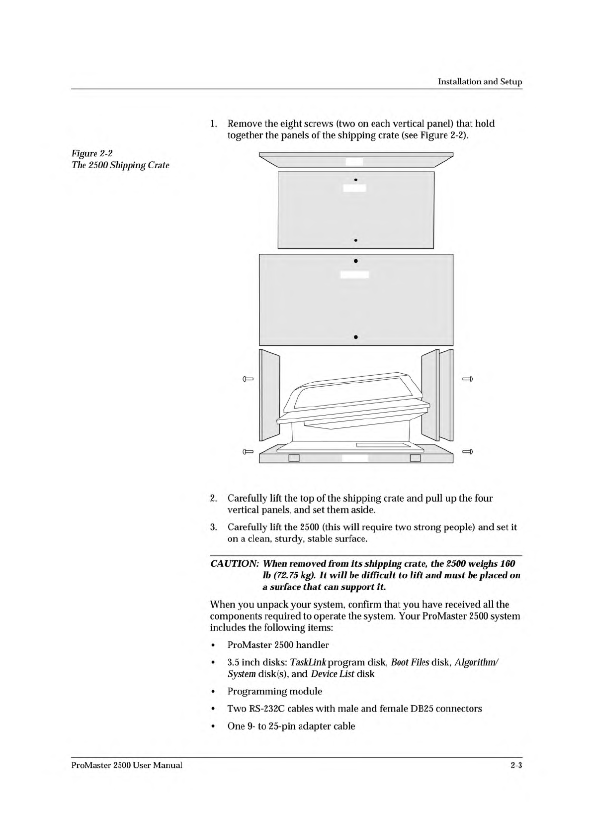
Figure
2-2
The
2500
Shipping
Crate
1.
Remove
the
eight
screws
(two
on
each
vertical
panel)
that
hold
together
the
panels
of
the
shipping
crate
(see
Figure
2-2).
2.
Carefully
lift
the
top
of
the
shipping
crate
and
pull
up
the
four
vertical
panels,
and
set
them
aside.
3.
Carefully
lift
the
2500
(this
will
require
two
strong
people)
and
set
it
on
a
clean,
sturdy,
stable
surface.
CAUTION:
When
removed
from
its
shipping
crate
f
the
2500
weighs
160
lb
(72.
75
kg).
It
be
difficult
to
lift
and
must
be
placed
on
a
surface
that
can
support
it.
When
you
unpack
your
system,
confirm
that
you
have
received
all
the
components
required
to
operate
the
system.
Your
ProMaster
2500
system
includes
the
following
items:
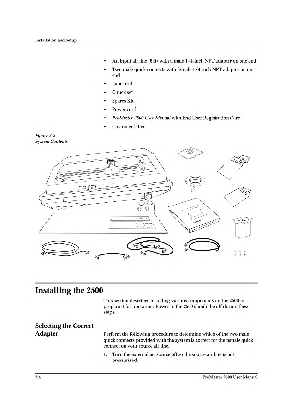
•
ProMaster
2500
handler
•
3.5
inch
disks:
TaskLink
program
disk,
Boot
Files
disk,
Algorithm/
System
disk(s),
and
Device
List
disk
•
Programming
module
•
Two
RS-
232c
cables
with
male
and
female
DB25
connectors
ProMaster
2500
User
Manual
•
One
9-
to
25-pin
adapter
cable
2-3
PROMASTER 2500
DISKS
POWER CORD
USER
MANUAL
1763-3
RS-232 CABLE (2)
P
r
o
M
a
s
t
e
r
2
5
0
0
TASKLINK
DISK
LABEL
ROLL
1/4" INPUT AIR LINE
(With 2 adapters)
PROGRAMMING
MODULE
9 - 25 PIN
CABLE
SPARES KIT
CHUCK SET
Installation
and
Setup
•
An
input
air
line
(6
ft)
with
a
male
1/4-inch
NPT
adapter
on
one
end
•
Two
male
quick
connects
with
female
1/
4-inch
NPT
adapter
on
one
end
•
Label
roll
•
Chuck
set
•
Spares
Kit
•
Power
cord
•
ProMaster
2500
User
Manual
with
End
User
Registration
Card
•
Customer
letter
Figure
2-3
System
Contents
Installing
the
2500
This
section
describes
installing
various
components
on
the
2500
to
prepare
it
for
operation.
Power
to
the
2500
should
be
off
during
these
steps.
Selecting
the
Correct
Adapter
Perform
the
following
procedure
to
determine
which
of
the
two
male
quick
connects
provided
with
the
system
is
correct
for
the
female
quick
connect
on
your
source
air
line.
1.
Turn
the
external
air
source
off
so
the
source
air
line
is
not
pressurized.
2-4
ProMaster
2500
User
Manual