2500_Users_Manual-.pdf - 第393页
Computer Remote Control @@Q7XXYYY Y = Bin Assignment — Configures the bin map for the specified bin. XX represents the bin and YYY represents the bin configuration number. The bin number is a two-digit ASCII number from …
Computer
Remote
Control
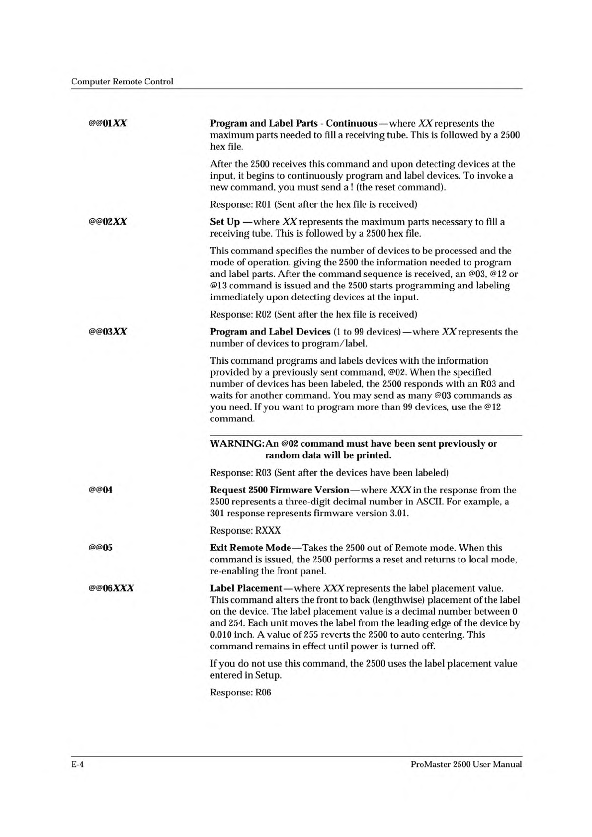
@@01XX
Program
and
Label
Parts
-
Continuous
—
where
XX
represents
the
maximum
parts
needed
to
fill
a
receiving
tube.
This
is
followed
by
a
2500
hex
file.
After
the
2500
receives
this
command
and
upon
detecting
devices
at
the
input,
it
begins
to
continuously
program
and
label
devices.
To
invoke
a
new
command,
you
must
send
a
!
(the
reset
command).
Response:
R01
(Sent
after
the
hex
file
is
received)
@@02XX
Set
Up
—
where
XX
represents
the
maximum
parts
necessary
to
fill
a
receiving
tube.
This
is
followed
by
a
2500
hex
file.
This
command
specifies
the
number
of
devices
to
be
processed
and
the
mode
of
operation,
giving
the
2500
the
information
needed
to
program
and
label
parts.
After
the
command
sequence
is
received,
an
@03,
@12
or
@13
command
is
issued
and
the
2500
starts
programming
and
labeling
immediately
upon
detecting
devices
at
the
input.
Response:
R02
(Sent
after
the
hex
file
is
received)
@@03AX
Program
and
Label
Devices
(1
to
99
devices)
—
where
XX
represents
the
number
of
devices
to
program/
label.
This
command
programs
and
labels
devices
with
the
information
provided
by
a
previously
sent
command,
@02.
When
the
specified
number
of
devices
has
been
labeled,
the
2500
responds
with
an
R03
and
waits
for
another
command.
You
may
send
as
many
@03
commands
as
you
need.
If
you
want
to
program
more
than
99
devices,
use
the
@12
command.
WARNING:
An
@02
command
must
have
been
sent
previously
or
random
data
will
be
printed.
Response:
R03
(Sent
after
the
devices
have
been
labeled)
@@04
Request
2500
Firmware
Version
—
where
XXX
in
the
response
from
the
2500
represents
a
three-digit
decimal
number
in
ASCII.
For
example,
a
301
response
represents
firmware
version
3.01.
Response:
RXXX
@@05
Exit
Remote
Mode
—
Takes
the
2500
out
of
Remote
mode.
When
this
command
is
issued,
the
2500
performs
a
reset
and
returns
to
local
mode,
re-enabling
the
front
panel.
@@06XXX
Label
Placement
—
where
XXX
represents
the
label
placement
value.
This
command
alters
the
front
to
back
(lengthwise)
placement
of
the
label
on
the
device.
The
label
placement
value
is
a
decimal
number
between
0
and
254.
Each
unit
moves
the
label
from
the
leading
edge
of
the
device
by
0.010
inch.
A
value
of
255
reverts
the
2500
to
auto
centering.
This
command
remains
in
effect
until
power
is
turned
off.
If
you
do
not
use
this
command,
the
2500
uses
the
label
placement
value
entered
in
Setup.
Response:
R06
E-4
ProMaster
2500
User
Manual
Computer
Remote
Control
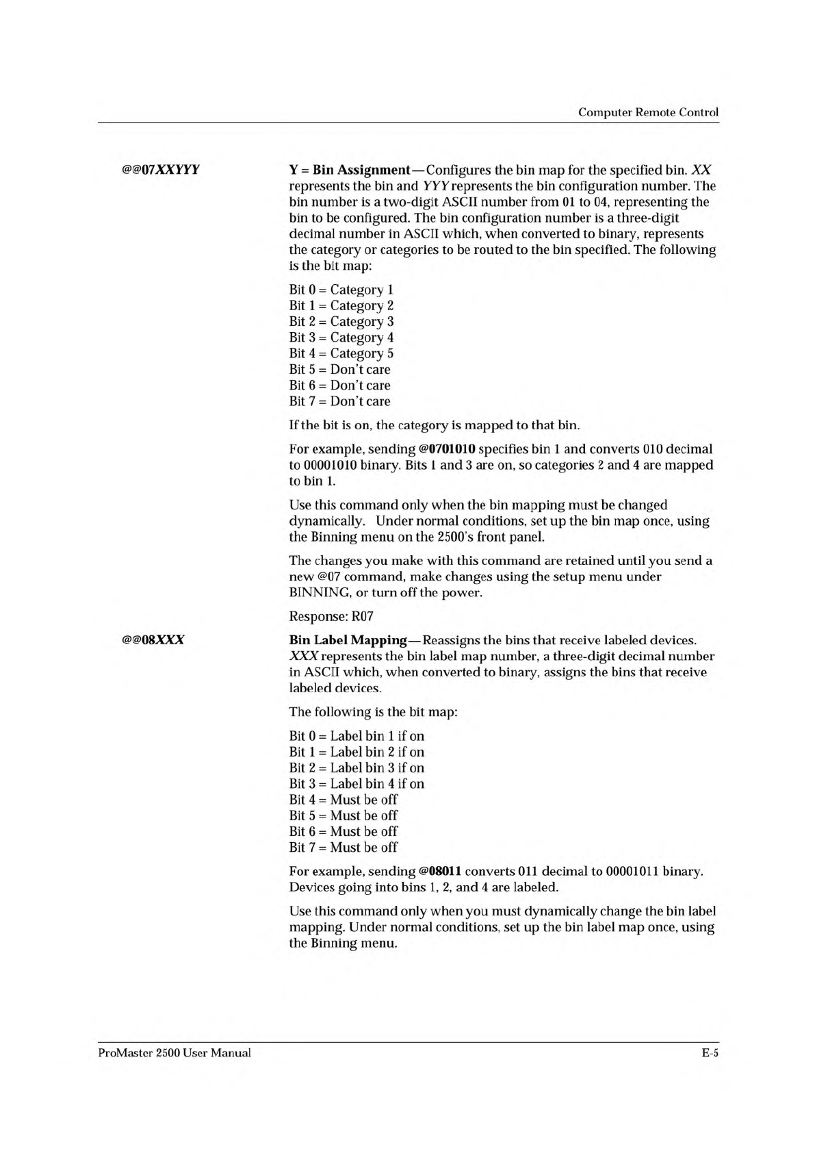
@@Q7XXYYY
Y
=
Bin
Assignment
—
Configures
the
bin
map
for
the
specified
bin.
XX
represents
the
bin
and
YYY
represents
the
bin
configuration
number.
The
bin
number
is
a
two-digit
ASCII
number
from
01
to
04,
representing
the
bin
to
be
configured.
The
bin
configuration
number
is
a
three-digit
decimal
number
in
ASCII
which,
when
converted
to
binary,
represents
the
category
or
categories
to
be
routed
to
the
bin
specified.
The
following
is
the
bit
map:
Bit
0
=
Category
1
Bit
1
=
Category
2
Bit
2
=
Category
3
Bit
3
=
Category
4
Bit
4
=
Category
5
Bit
5
=
Don't
care
Bit
6
=
Don't
care
Bit
7
=
Don't
care
If
the
bit
is
on,
the
category
is
mapped
to
that
bin.
For
example,
sending
@0701010
specifies
bin
1
and
converts
010
decimal
to
00001010
binary.
Bits
1
and
3
are
on,
so
categories
2
and
4
are
mapped
to
bin
1.
Use
this
command
only
when
the
bin
mapping
must
be
changed
dynamically.
Under
normal
conditions,
set
up
the
bin
map
once,
using
the
Binning
menu
on
the
2500's
front
panel.
The
changes
you
make
with
this
command
are
retained
until
you
send
a
new
@07
command,
make
changes
using
the
setup
menu
under
BINNING,
or
turn
off
the
power.
Response:
R07
@@08XXX
Bin
Label
Mapping
—
Reassigns
the
bins
that
receive
labeled
devices.
XXX
represents
the
bin
label
map
number,
a
three-digit
decimal
number
in
ASCII
which,
when
converted
to
binary,
assigns
the
bins
that
receive
labeled
devices.
The
following
is
the
bit
map:
Bit
0
=
Label
bin
1
if
on
Bit
1
=
Label
bin
2
if
on
Bit
2
=
Label
bin
3
if
on
Bit
3
=
Label
bin
4
if
on
Bit
4
=
Must
be
off
Bit
5
=
Must
be
off
Bit
6
=
Must
be
off
Bit
7
=
Must
be
off
For
example,
sending
@08011
converts
011
decimal
to
00001011
binary.
Devices
going
into
bins
1,
2,
and
4
are
labeled.
Use
this
command
only
when
you
must
dynamically
change
the
bin
label
mapping.
Under
normal
conditions,
set
up
the
bin
label
map
once,
using
the
Binning
menu.
ProMaster
2500
User
Manual
E-5
Computer
Remote
Control
The
changes
you
make
with
this
command
are
retained
until
you
send
a
new
@08
command,
make
changes
using
the
setup
menu
under
BINNING,
or
turn
off
power.
Sending
an
@08255
restores
the
label
mapping
settings
to
those
currently
defined
in
the
BINNING
setup
menu.
Response:
R08
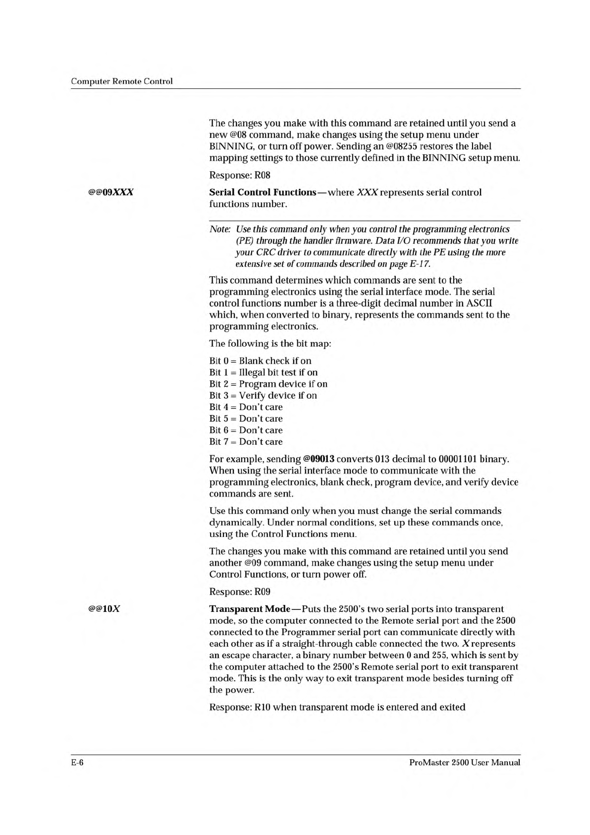
@@09XXX
Serial
Control
Functions
—
where
XXX
represents
serial
control
functions
number.
Note:
Use
this
command
only
when
you
control
the
programming
electronics
(PE)
through
the
handler
firmware.
Data
I/O
recommends
that
you
write
your
CRC
driver
to
communicate
directly
with
the
PE
using
the
more
extensive
set
of
commands
described
on
page
E-l
7.
This
command
determines
which
commands
are
sent
to
the
programming
electronics
using
the
serial
interface
mode.
The
serial
control
functions
number
is
a
three-digit
decimal
number
in
ASCII
which,
when
converted
to
binary,
represents
the
commands
sent
to
the
programming
electronics.
The
following
is
the
bit
map:
Bit
0
=
Blank
check
if
on
Bit
1
=
Illegal
bit
test
if
on
Bit
2
=
Program
device
if
on
Bit
3
=
Verify
device
if
on
Bit
4
=
Don't
care
Bit
5
=
Don't
care
Bit
6
=
Don't
care
Bit
7
=
Don't
care
For
example,
sending
@09013
converts
013
decimal
to
00001101
binary.
When
using
the
serial
interface
mode
to
communicate
with
the
programming
electronics,
blank
check,
program
device,
and
verify
device
commands
are
sent.
Use
this
command
only
when
you
must
change
the
serial
commands
dynamically.
Under
normal
conditions,
set
up
these
commands
once,
using
the
Control
Functions
menu.
The
changes
you
make
with
this
command
are
retained
until
you
send
another
@09
command,
make
changes
using
the
setup
menu
under
Control
Functions,
or
turn
power
off.
Response:
R09
@@10X
Transparent
Mode
—
Puts
the
2500's
two
serial
ports
into
transparent
mode,
so
the
computer
connected
to
the
Remote
serial
port
and
the
2500
connected
to
the
Programmer
serial
port
can
communicate
directly
with
each
other
as
if
a
straight-through
cable
connected
the
two.
X
represents
an
escape
character,
a
binary
number
between
0
and
255,
which
is
sent
by
the
computer
attached
to
the
2500's
Remote
serial
port
to
exit
transparent
mode.
This
is
the
only
way
to
exit
transparent
mode
besides
turning
off
the
power.
Response:
R10
when
transparent
mode
is
entered
and
exited
E-6
ProMaster
2500
User
Manual