2500_Users_Manual-.pdf - 第400页
Q20202FB Q20210ED Q30301EB10 Computer Remote Control Q2 Q3 Q4 Q5 This record contains the index number in hex of the type of device to be handled. The following device types and their index numbers are available for hand…
Computer
Remote
Control
Hex
Label
Format
Label
Record
Content
Label
Record
Types
QO
Qi
The
Hex
Label
format
has
been
developed
to
encode
data
files
in
ASCII
format
to
transfer
between
the
Remote
RS
232c
port
on
the
2500
and
the
attached
computer
system.
Label
records
appear
as
character
strings
consisting
of
the
following
four
fields:
identifying
record
type,
record
length,
data,
and
checksum.
Each
byte
of
binary
data
is
encoded
as
a
2-character
hexadecimal
number;
the
first
character
represents
the
four
high-order
bits,
and
the
second
represents
the
four
low-order
bits
of
the
byte.
The
four
fields
are
described
below.
Field
No.
of
ASCII
Characters
Description
Record
Type
2
Label
Record
Type
Q0,
Q1...Q9.
Record
Length
2
The
count
of
the
character
pairs
in
the
record,
excluding
the
record
type
and
record
length.
Data
0-2n
From
0
to
n
bytes
of
data.
Checksum
2
The
least
significant
byte
of
the
one's
complement
of
the
sum
of
the
values,
represented
by
the
pairs
of
characters
making
up
the
record
length
and
the
data
fields.
Each
record
can
be
terminated
with
a
CR/LF/NULL.
Accuracy
of
transmission
is
ensured
by
the
record
length
(byte
count)
and
checksum
fields.
Eight
types
of
label
records
facilitate
information
exchange
between
the
2500
and
other
computer
systems.
Two
more
have
been
identified
for
future
requirements.
These
records
are
described
below.
The
header
record
for
each
block
of
label
records.
The
data
field
can
contain
any
descriptive
information
identifying
the
following
block
of
label
records.
A
record
containing
labeling
information.
The
data
field
may
contain
up
to
8
lines
of
18
characters
specifying
the
contents
of
the
label.
A
0D
hex
is
used
as
a
delimiter
between
lines.
A
copyright
character
can
be
selected
by
a
IF
hex.
ProMaster
2500
User
Manual
E-ll
Q20202FB
Q20210ED
Q30301EB10
Computer
Remote
Control
Q2
Q3
Q4
Q5
This
record
contains
the
index
number
in
hex
of
the
type
of
device
to
be
handled.
The
following
device
types
and
their
index
numbers
are
available
for
handling:
01
-
PLCC
20
02
-
PLCC
28
03
-
PLCC
32
04
-
PLCC
44
05
-
PLCC
52
06
-
PLCC
68
07
-
PLCC
84
08
-
DIP
08
09
-
DIP
14
10
-
DIP
16
11
-DIP
18
12
-DIP
20
13
-DIP
22
14
-
DIP
24-0.3”
15
-DIP
24-06'
16
-DIP
28-0.6”
17
-DIP
32
18
-DIP
28-0.3”
19
-SOL
8
20
-
SOL
14
21
-SOL
16
22
-
SOL
18
23
-
SOL
20
24
-
SOL
24
25
-
SOL
28
26
-
SOL
32
27
-
SOL
40
28
-
SOL
44
To
select
a
28-pin
PLCC
device,
send
the
following
Q2
record:
.
If
the
index
number
is
16,
the
record
converts
16
decimal
to
10
hex
and
looks
like
this:
.
The
remote
computer
can
download
the
most
current
device
list
contained
in
the
2500
by
sending
an
@15
command.
If
you
need
to
handle
a
device
type
not
currently
defined,
you
can
use
a
Q3
record
in
place
of
the
Q2
record
to
define
the
device
type.
A
Q2
or
Q3
record
must
be
present
or
an
error
is
displayed.
This
record
type
is
used
instead
of
a
Q2
record
to
define
a
custom
device
length.
It
contains
a
4-digit
field
defining
the
device
length
in
thousands
of
an
inch,
represented
in
hex.
The
length
of
a
device
is
defined
as
the
distance
between
the
outermost
extensions
of
the
device
(pins
included)
in
the
direction
of
travel
through
the
2500's
track.
The
device
length
must
be
represented
as
an
integer
before
it
is
converted
to
a
hex
value.
To
define
a
device
with
a
length
of
.491
inches
long:
1.
Convert
0.491
into
an
integer
by
dividing
it
by
0.001.
The
result
is
491.
2.
Convert
491
(decimal)
to
01EB
(hex).
3.
Complete
record
=
A
Q2
or
Q3
record
must
be
present
or
an
error
message
is
displayed.
Reserved
for
future
use.
Reserved
for
future
use.
E-12
ProMaster
2500
User
Manual
DIRECTION OF TRAVEL
3
INTO RECEIVING
TUBE
1
0 2
3
LABEL
ORIENTATION
1
TXT
0 2
3
OUT OF
INPUT TUBE
1
0 2
1391-1
00010011
RESERVED FOR FUTURE USE
INTO RECEIVING TUBE
LABEL ORIENTATION
OUT OF INPUT TUBE
1392-1
Computer
Remote
Control
Q6
This
record
contains
print
density
information.
It
is
allowed
one
data
byte
and
is
defined
as
follows:
Dot
Matrix
Printer
00
=
Auto-Select
01
=
26
CPI
02
=
26
S
CPI
(Short)
03
=
20
CPI
04=
16T
CPI
(Tall)
05
=
12
T
CPI
(Tall)
07
=
18
CPI
Thermal
Printer
00
=
Auto-Select
01
=
28
CPI
02
=
28
S
CPI
(Short)
03
=
22
CPI
04=
11
CPI
05
=
19
CPI
06
=
16
CPI
To
select
a
print
density
of
26
CPI
for
the
dot
matrix
printer,
the
record
would
be
Q60201FC.
If
this
record
is
not
received,
the
12
CPI
print
density
is
assumed.
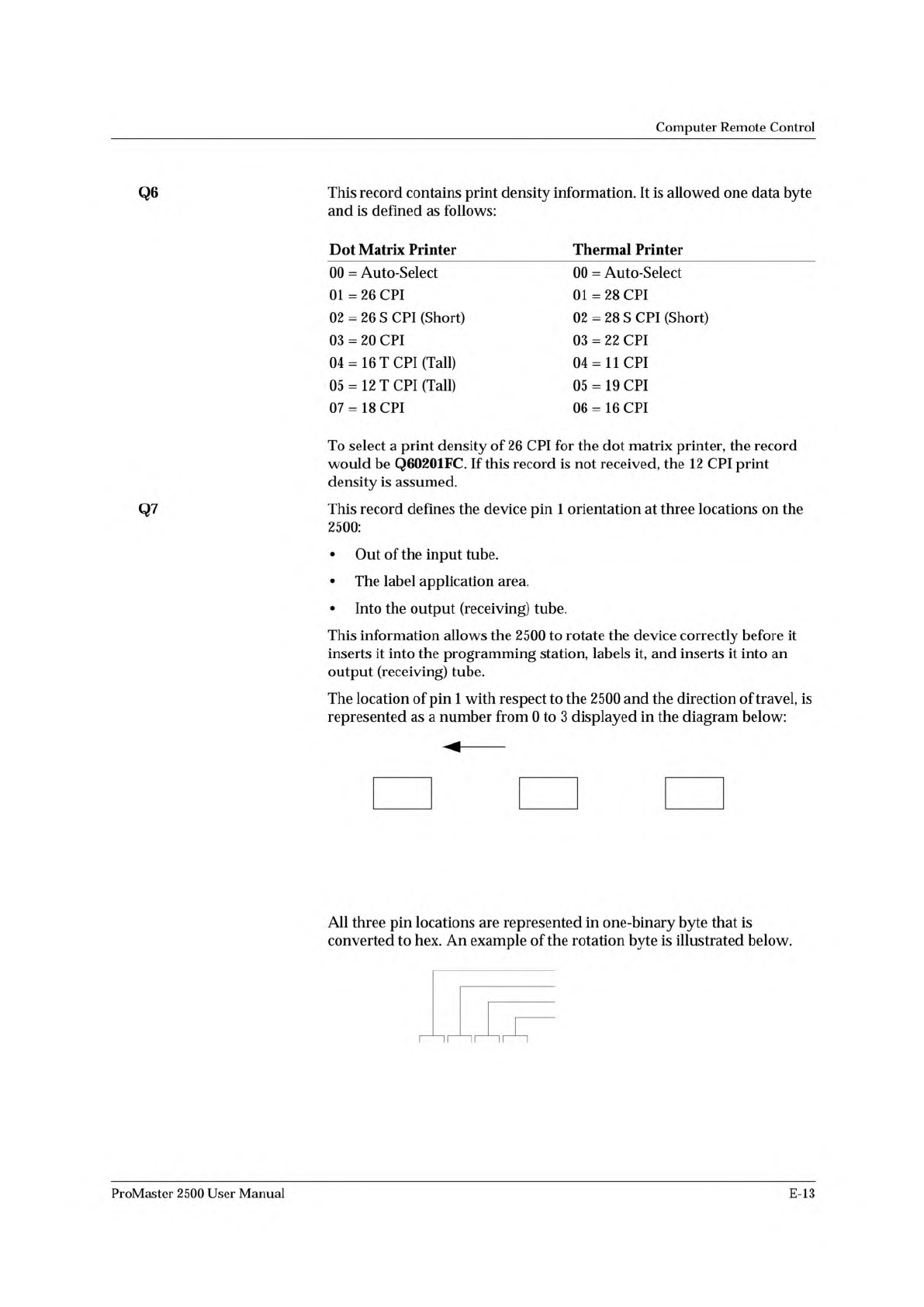
Q7
This
record
defines
the
device
pin
1
orientation
at
three
locations
on
the
2500:
•
Out
of
the
input
tube.
•
The
label
application
area.
•
Into
the
output
(receiving)
tube.
This
information
allows
the
2500
to
rotate
the
device
correctly
before
it
inserts
it
into
the
programming
station,
labels
it,
and
inserts
it
into
an
output
(receiving)
tube.
The
location
of
pin
1
with
respect
to
the
2500
and
the
direction
of
travel,
is
represented
as
a
number
from
0
to
3
displayed
in
the
diagram
below:
All
three
pin
locations
are
represented
in
one-binary
byte
that
is
converted
to
hex.
An
example
of
the
rotation
byte
is
illustrated
below.
ii
~
~
ii
~
~
i
「
ProMaster
2500
User
Manual
E-13