2500_Users_Manual-.pdf - 第402页
Q70213EA . Q001FE Q10C4C4142454C0D544558 540D34 Q20201FC Q60202FB Q70213EA Q901FE Q0 01 FE INTO RECEIVING TUBE = 01 (1) PIN 1 LABEL ORIENTATION = 0 DIRECTION OF TRAVEL TXT PIN 1 PIN 1 OUT OF INPUT TUBE = 11 (3) 1393-1 Co…
DIRECTION OF TRAVEL
3
INTO RECEIVING
TUBE
1
0 2
3
LABEL
ORIENTATION
1
TXT
0 2
3
OUT OF
INPUT TUBE
1
0 2
1391-1
00010011
RESERVED FOR FUTURE USE
INTO RECEIVING TUBE
LABEL ORIENTATION
OUT OF INPUT TUBE
1392-1
Computer
Remote
Control
Q6
This
record
contains
print
density
information.
It
is
allowed
one
data
byte
and
is
defined
as
follows:
Dot
Matrix
Printer
00
=
Auto-Select
01
=
26
CPI
02
=
26
S
CPI
(Short)
03
=
20
CPI
04=
16T
CPI
(Tall)
05
=
12
T
CPI
(Tall)
07
=
18
CPI
Thermal
Printer
00
=
Auto-Select
01
=
28
CPI
02
=
28
S
CPI
(Short)
03
=
22
CPI
04=
11
CPI
05
=
19
CPI
06
=
16
CPI
To
select
a
print
density
of
26
CPI
for
the
dot
matrix
printer,
the
record
would
be
Q60201FC.
If
this
record
is
not
received,
the
12
CPI
print
density
is
assumed.
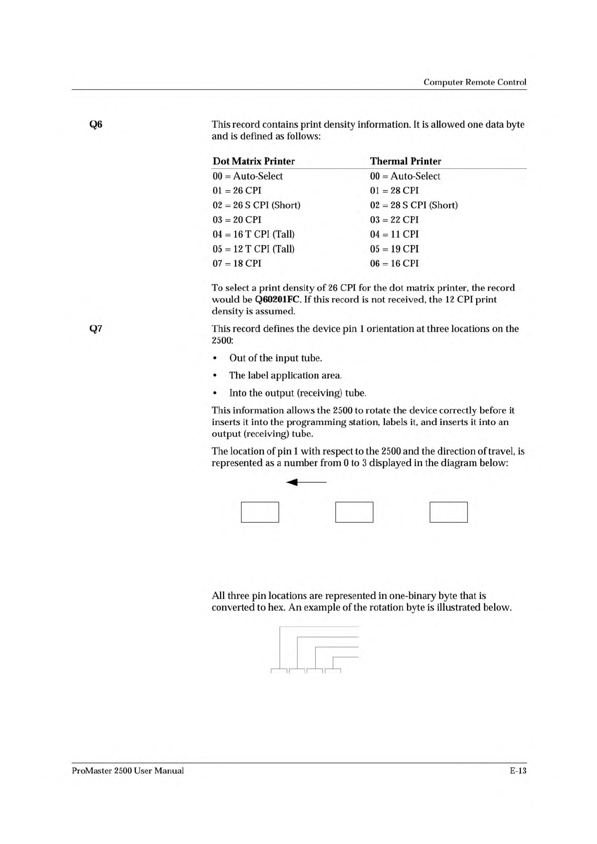
Q7
This
record
defines
the
device
pin
1
orientation
at
three
locations
on
the
2500:
•
Out
of
the
input
tube.
•
The
label
application
area.
•
Into
the
output
(receiving)
tube.
This
information
allows
the
2500
to
rotate
the
device
correctly
before
it
inserts
it
into
the
programming
station,
labels
it,
and
inserts
it
into
an
output
(receiving)
tube.
The
location
of
pin
1
with
respect
to
the
2500
and
the
direction
of
travel,
is
represented
as
a
number
from
0
to
3
displayed
in
the
diagram
below:
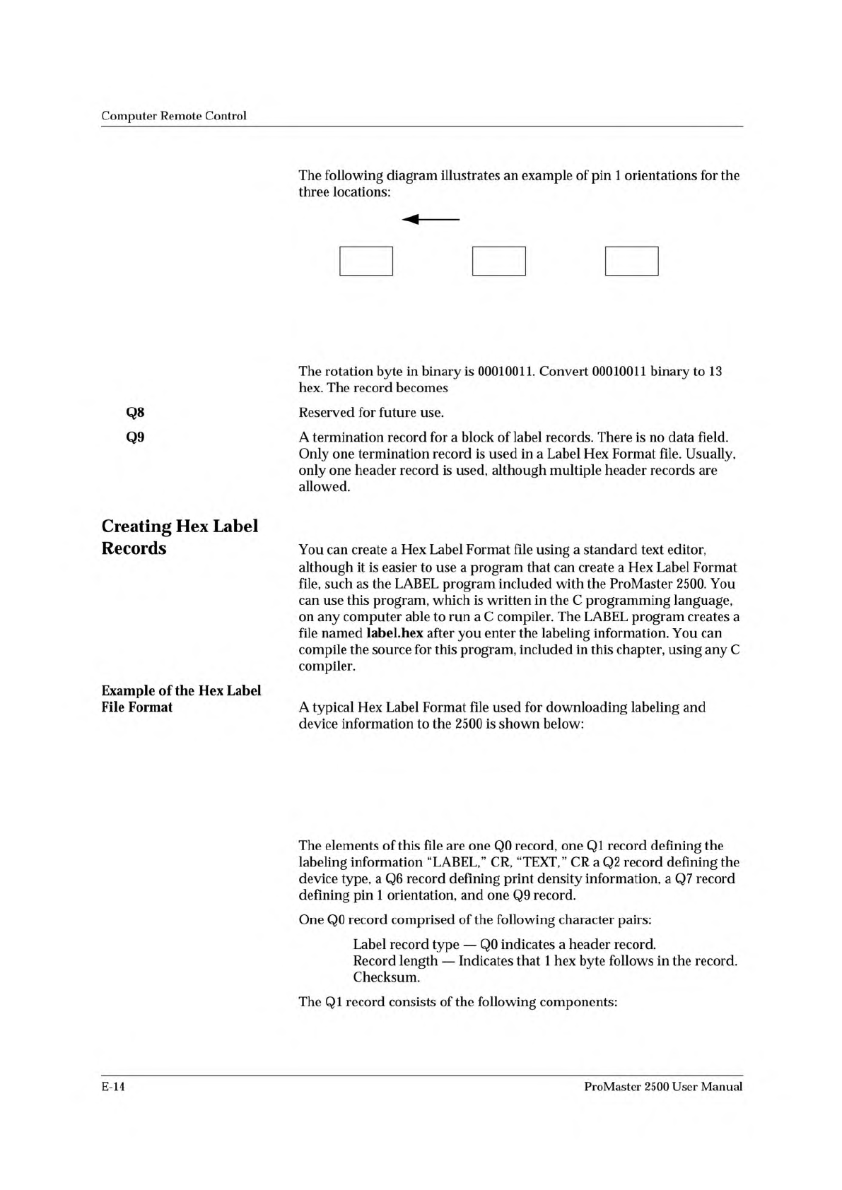
All
three
pin
locations
are
represented
in
one-binary
byte
that
is
converted
to
hex.
An
example
of
the
rotation
byte
is
illustrated
below.
ii
~
~
ii
~
~
i
「
ProMaster
2500
User
Manual
E-13
Q70213EA.
Q001FE
Q10C4C4142454C0D544558540D34
Q20201FC
Q60202FB
Q70213EA
Q901FE
Q0
01
FE
INTO RECEIVING
TUBE = 01 (1)
PIN 1
LABEL
ORIENTATION = 0
DIRECTION OF TRAVEL
TXT
PIN 1
PIN 1
OUT OF
INPUT TUBE = 11 (3)
1393-1
Computer
Remote
Control
Q8
Q9
Creating
Hex
Label
Records
Example
of
the
Hex
Label
File
Format
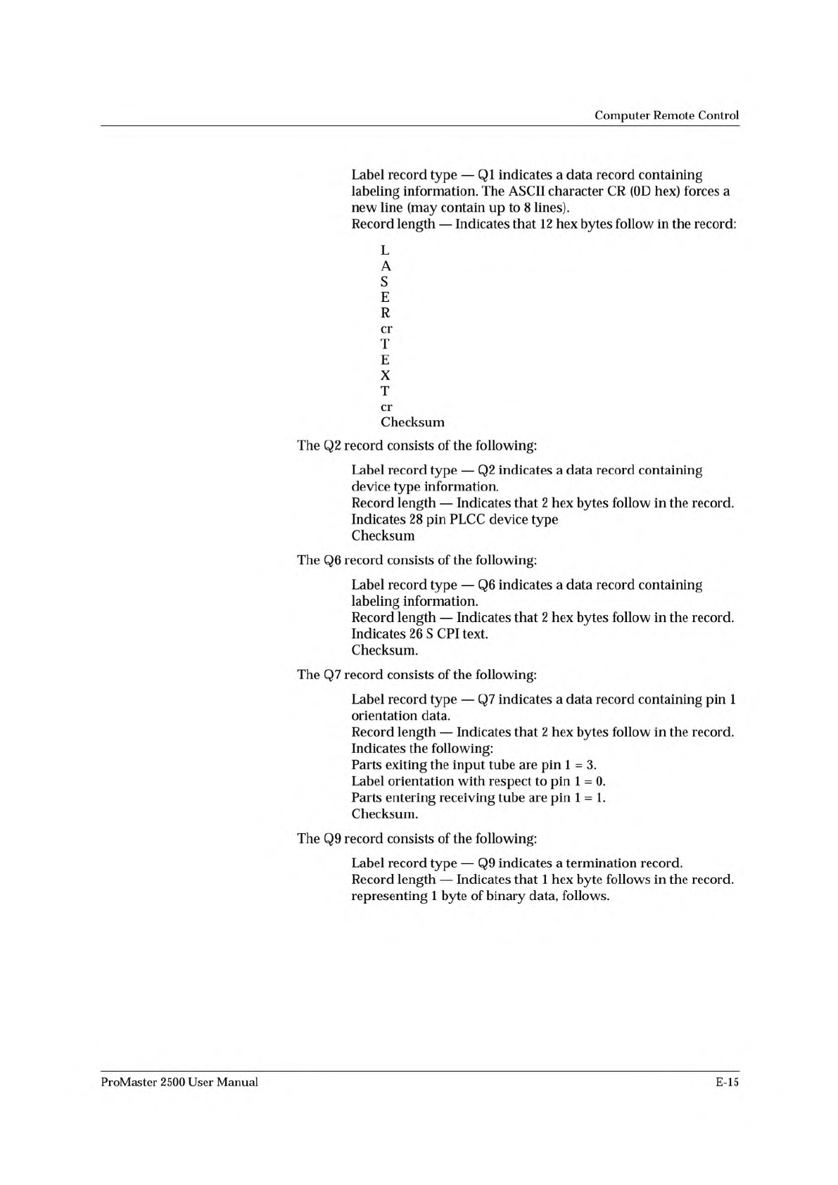
The
following
diagram
illustrates
an
example
of
pin
1
orientations
for
the
three
locations:
The
rotation
byte
in
binary
is
00010011.
Convert
00010011
binary
to
13
hex.
The
record
becomes
Reserved
for
future
use.
A
termination
record
for
a
block
of
label
records.
There
is
no
data
field.
Only
one
termination
record
is
used
in
a
Label
Hex
Format
file.
Usually,
only
one
header
record
is
used,
although
multiple
header
records
are
allowed.
You
can
create
a
Hex
Label
Format
file
using
a
standard
text
editor,
although
it
is
easier
to
use
a
program
that
can
create
a
Hex
Label
Format
file,
such
as
the
LABEL
program
included
with
the
ProMaster
2500.
You
can
use
this
program,
which
is
written
in
the
C
programming
language,
on
any
computer
able
to
run
a
C
compiler.
The
LABEL
program
creates
a
file
named
label.hex
after
you
enter
the
labeling
information.
You
can
compile
the
source
for
this
program,
included
in
this
chapter,
using
any
C
compiler.
A
typical
Hex
Label
Format
file
used
for
downloading
labeling
and
device
information
to
the
2500
is
shown
below:
The
elements
of
this
file
are
one
Q0
record,
one
QI
record
defining
the
labeling
information
“LABEL,”
CR,
“TEXT,”
CR
a
Q2
record
defining
the
device
type,
a
Q6
record
defining
print
density
information,
a
Q7
record
defining
pin
1
orientation,
and
one
Q9
record.
One
Q0
record
comprised
of
the
following
character
pairs:
Label
record
type
—
Q0
indicates
a
header
record.
Record
length
—
Indicates
that
1
hex
byte
follows
in
the
record.
Checksum.
The
QI
record
consists
of
the
following
components:
E-14
ProMaster
2500
User
Manual
Q1
0C
4C
41
42
45
4C
0D
54
45
58
54
0D
34
Q2
02
01
FC
Q6
02
02
FB
Q7
02
13
EA
Q9
01
Computer
Remote
Control
Label
record
type
—
QI
indicates
a
data
record
containing
labeling
information.
The
ASCII
character
CR
(OD
hex)
forces
a
new
line
(may
contain
up
to
8
lines).
Record
length
—
Indicates
that
12
hex
bytes
follow
in
the
record:
L
A
S
E
R
cr
T
E
X
T
cr
Checksum
The
Q2
record
consists
of
the
following:
Label
record
type
—
Q2
indicates
a
data
record
containing
device
type
information.
Record
length
—
Indicates
that
2
hex
bytes
follow
in
the
record.
Indicates
28
pin
PLCC
device
type
Checksum
The
Q6
record
consists
of
the
following:
Label
record
type
—
Q6
indicates
a
data
record
containing
labeling
information.
Record
length
—
Indicates
that
2
hex
bytes
follow
in
the
record.
Indicates
26
s
CPI
text.
Checksum.
The
Q7
record
consists
of
the
following:
Label
record
type
—
Q7
indicates
a
data
record
containing
pin
1
orientation
data.
Record
length
—
Indicates
that
2
hex
bytes
follow
in
the
record.
Indicates
the
following:
Parts
exiting
the
input
tube
are
pin
1
=
3.
Label
orientation
with
respect
to
pin
1
=
0.
Parts
entering
receiving
tube
are
pin
1
=
1.
Checksum.
The
Q9
record
consists
of
the
following:
Label
record
type
—
Q9
indicates
a
termination
record.
Record
length
—
Indicates
that
1
hex
byte
follows
in
the
record,
representing
1
byte
of
binary
data,
follows.
ProMaster
2500
User
Manual
E-15