2500_Users_Manual-.pdf - 第409页
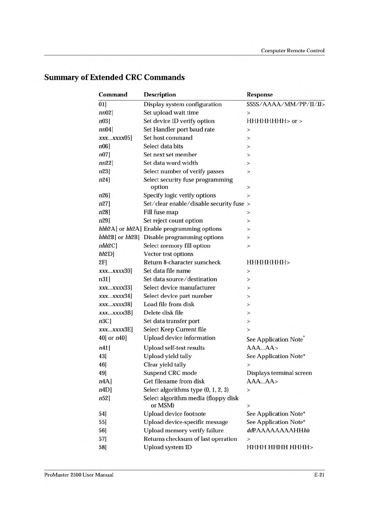
Computer Remote Control Summary of Extended CRC Commands Command Description Response 01] Display system configuration SSSS/AAAA/MM/PP/II/JJ> nn02] Set upload wait time > n03] Set device ID verify option or > nn…
Computer
Remote
Control
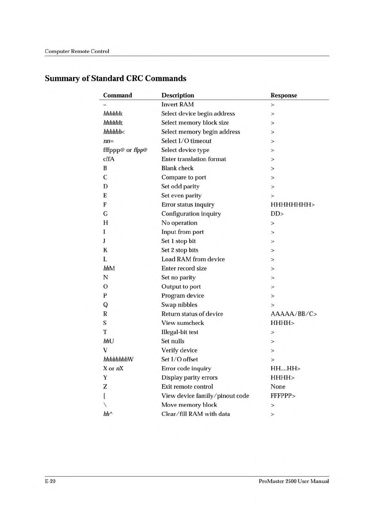
Summary
of
Standard
CRC
Commands
Command
Description
Response
—
Invert
RAM
>
hhhhhh:
Select
device
begin
address
>
hhhhhh;
Select
memory
block
size
>
hhhhhh<
Select
memory
begin
address
>
nn=
Select
I/O
timeout
>
fffppp@
or
ffpp@
Select
device
type
>
cffA
Enter
translation
format
>
B
Blank
check
>
C
Compare
to
port
>
D
Set
odd
parity
>
E
Set
even
parity
>
F
Error
status
inquiry
HHHHHHHH>
G
Configuration
inquiry
DD>
H
No
operation
>
I
Input
from
port
>
J
Set
1
stop
bit
>
K
Set
2
stop
bits
>
L
Load
RAM
from
device
>
hhM
Enter
record
size
>
N
Set
no
parity
>
0
Output
to
port
>
P
Program
device
>
Q
Swap
nibbles
>
R
Return
status
of
device
AAAAA/BB/C>
S
View
sumcheck
HHHH>
T
Illegal-bit
test
>
力力
U
Set
nulls
>
V
Verify
device
>
hhhhhhhhW
Set
I/O
offset
>
X
or
nX
Error
code
inquiry
HH....HH>
Y
Display
parity
errors
HHHH>
Z
Exit
remote
control
None
[
View
device
family/pinout
code
FFFPPP>
\
Move
memory
block
>
hh
人
Clear/fill
RAM
with
data
>
E-20
ProMaster
2500
User
Manual
Computer
Remote
Control
Summary
of
Extended
CRC
Commands
Command
Description
Response
01]
Display
system
configuration
SSSS/AAAA/MM/PP/II/JJ>
nn02]
Set
upload
wait
time
>
n03]
Set
device
ID
verify
option
or
>
nn04]
Set
Handler
port
baud
rate
>
XXX...XXXX05]
Set
host
command
>
加
6]
Select
data
bits
>
n07]
Set
next
set
member
>
nn22]
Set
data
word
width
>
成
3]
Select
number
of
verify
passes
>
成
4]
Select
security
fuse
programming
option
>
成
6]
Specify
logic
verify
options
>
成
7]
Set/
clear
enable/disable
security
fuse
>
成
8]
Fill
fuse
map
>
成
9]
Set
reject
count
option
>
力力力
2A]
or
力力
2A]
Enable
programming
options
>
力力力
2B]
or
力力
2B]
Disable
programming
options
>
nhh2C]
Select
memory
fill
option
>
励
2D]
Vector
test
options
2F]
Return
8-character
sumcheck
xxx...xxxx3Q]
Set
data
file
name
>
n31]
Set
data
source
/
destination
>
xxx...xxxx33]
Select
device
manufacturer
>
XXX...XXXXM]
Select
device
part
number
>
xxx...xxxx38]
Load
file
from
disk
>
xxx...xxxx3B]
Delete
disk
file
>
n3C]
Set
data
transfer
port
>
xxx...xxxx3E]
Select
Keep
Current
file
>
40]
or
7140]
Upload
device
information
See
Application
Note*
n41]
Upload
self-test
results
AAA...AA>
43]
Upload
yield
tally
See
Application
Note*
46]
Clear
yield
tally
>
49]
Suspend
CRC
mode
Displays
terminal
screen
n4A]
Get
filename
from
disk
AAA...AA>
n4D]
Select
algorithms
type
(0,
1,
2,
3)
>
n52]
Select
algorithm
media
(floppy
disk
or
MSM)
>
54]
Upload
device
footnote
See
Application
Note*
55]
Upload
device-specific
message
See
Application
Note*
56]
Upload
memory
verify
failure
ddPAAAAAAAAHH
初
i
57]
Returns
checksum
of
last
operation
>
58]
Upload
system
ID
HHHH HHHH
HHHH>
ProMaster
2500
User
Manual
E-21
Computer
Remote
Control
This
Application
Note,
(<UniSystem
Computer
Remote
Control,”
is
available
from
Data
I/O
Customer
Support.
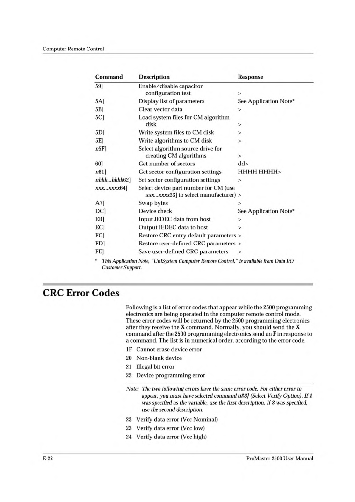
Command
Description
Response
59]
Enable/disable
capacitor
configuration
test
>
5A]
Display
list
of
parameters
See
Application
Note*
5B]
Clear
vector
data
>
5C]
Load
system
files
for
CM
algorithm
disk
>
5D]
Write
system
files
to
CM
disk
>
5E]
Write
algorithms
to
CM
disk
>
n5F]
Select
algorithm
source
drive
for
creating
CM
algorithms
>
60]
Get
number
of
sectors
dd>
n61]
Get
sector
configuration
settings
HHHH
HHHH>
nhhh...hhhhQ2]
Set
sector
configuration
settings
>
xxx...xxxx64]
Select
device
part
number
for
CM
(use
to
select
manufacturer)
>
A7]
Swap
bytes
>
DC]
Device
check
See
Application
Note*
EB]
Input
JEDEC
data
from
host
>
EC]
Output
JEDEC
data
to
host
>
FC]
Restore
CRC
entry
default
parameters
>
FD]
Restore
user-defined
CRC
parameters
>
FE]
Save
user-defined
CRC
parameters
>
CRC
Error
Codes
Following
is
a
list
of
error
codes
that
appear
while
the
2500
programming
electronics
are
being
operated
in
the
computer
remote
control
mode.
These
error
codes
will
be
returned
by
the
2500
programming
electronics
after
they
receive
the
X
command.
Normally,
you
should
send
the
X
command
after
the
2500
programming
electronics
send
an
F
in
response
to
a
command.
The
list
is
in
numerical
order,
according
to
the
error
code.
IF
Cannot
erase
device
error
20
Non-blank
device
2
1
Illegal
bit
error
22
Device
programming
error
Note:
The
two
following
errors
have
the
same
error
code.
For
either
error
to
appear,
you
must
have
selected
command
n23]
(Select
Verify
Option).
If
1
was
specified
as
the
variable,
use
the
first
description.
If
2
was
specified,
use
the
second
description.
23
Verify
data
error
(Vcc
Nominal)
23
Verify
data
error
(Vcc
low)
24
Verify
data
error
(Vcc
high)
E-22
ProMaster
2500
User
Manual