2500_Users_Manual-.pdf - 第424页
* * * HA NDLER SETUP MENU * * * 1 - BINNING 2 - CONTROL F UNCTIONS 3 - SETUP MEN U BIN 1=C1-X C2- C3- C4- C5- LABEL-X BIN 2=C1- C2-X C3-X C4-X C5-X LABEL- Local Mode Control Functions The 2500 displays: Press 1. The 2500…
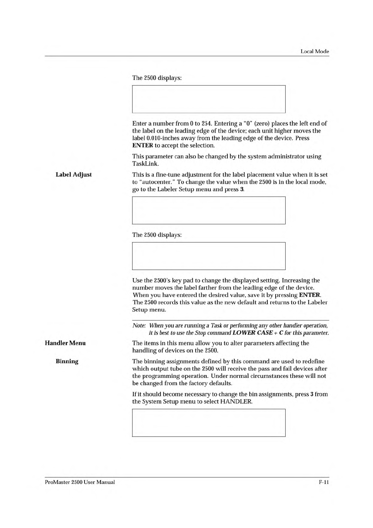
ENTER LABEL PLACEMENT VALUE (X):
ENTER "A" FOR AUTO CENTERING
* * * LABELER SETUP MENU * * *
1 - LABEL CALIBRATION 4 - SETUP MENU
2 - LABEL PLACEMENT
3 - LABEL ADJUST
ENTER LABEL ADJUST VALUE (X): _
* * * SYSTEM SETUP MENU * * *
1 - GENERAL 4 - MAIN MENU
2 - LABELER
3 - HANDLER
Local
Mode
Label
Adjust
Handler
Menu
Binning
The
2500
displays:
Enter
a
number
from
0
to
254.
Entering
a
“0”
(zero)
places
the
left
end
of
the
label
on
the
leading
edge
of
the
device;
each
unit
higher
moves
the
label
0.010-inches
away
from
the
leading
edge
of
the
device.
Press
ENTER
to
accept
the
selection.
This
parameter
can
also
be
changed
by
the
system
administrator
using
TaskLink.
This
is
a
fine-tune
adjustment
for
the
label
placement
value
when
it
is
set
to
“autocenter.”
To
change
the
value
when
the
2500
is
in
the
local
mode,
go
to
the
Labeler
Setup
menu
and
press
3.
The
2500
displays:
Use
the
2500's
key
pad
to
change
the
displayed
setting.
Increasing
the
number
moves
the
label
farther
from
the
leading
edge
of
the
device.
When
you
have
entered
the
desired
value,
save
it
by
pressing
ENTER.
The
2500
records
this
value
as
the
new
default
and
returns
to
the
Labeler
Setup
menu.
Note:
When
you
are
running
a
Task
or
performing
any
other
handler
operation,
it
Is
best
to
use
the
Stop
command
LOWER
CASE
+
C
for
this
parameter.
The
items
in
this
menu
allow
you
to
alter
parameters
affecting
the
handling
of
devices
on
the
2500.
The
binning
assignments
defined
by
this
command
are
used
to
redefine
which
output
tube
on
the
2500
will
receive
the
pass
and
fail
devices
after
the
programming
operation.
Under
normal
circumstances
these
will
not
be
changed
from
the
factory
defaults.
If
it
should
become
necessary
to
change
the
bin
assignments,
press
3
from
the
System
Setup
menu
to
select
HANDLER.
ProMaster
2500
User
Manual
F-ll
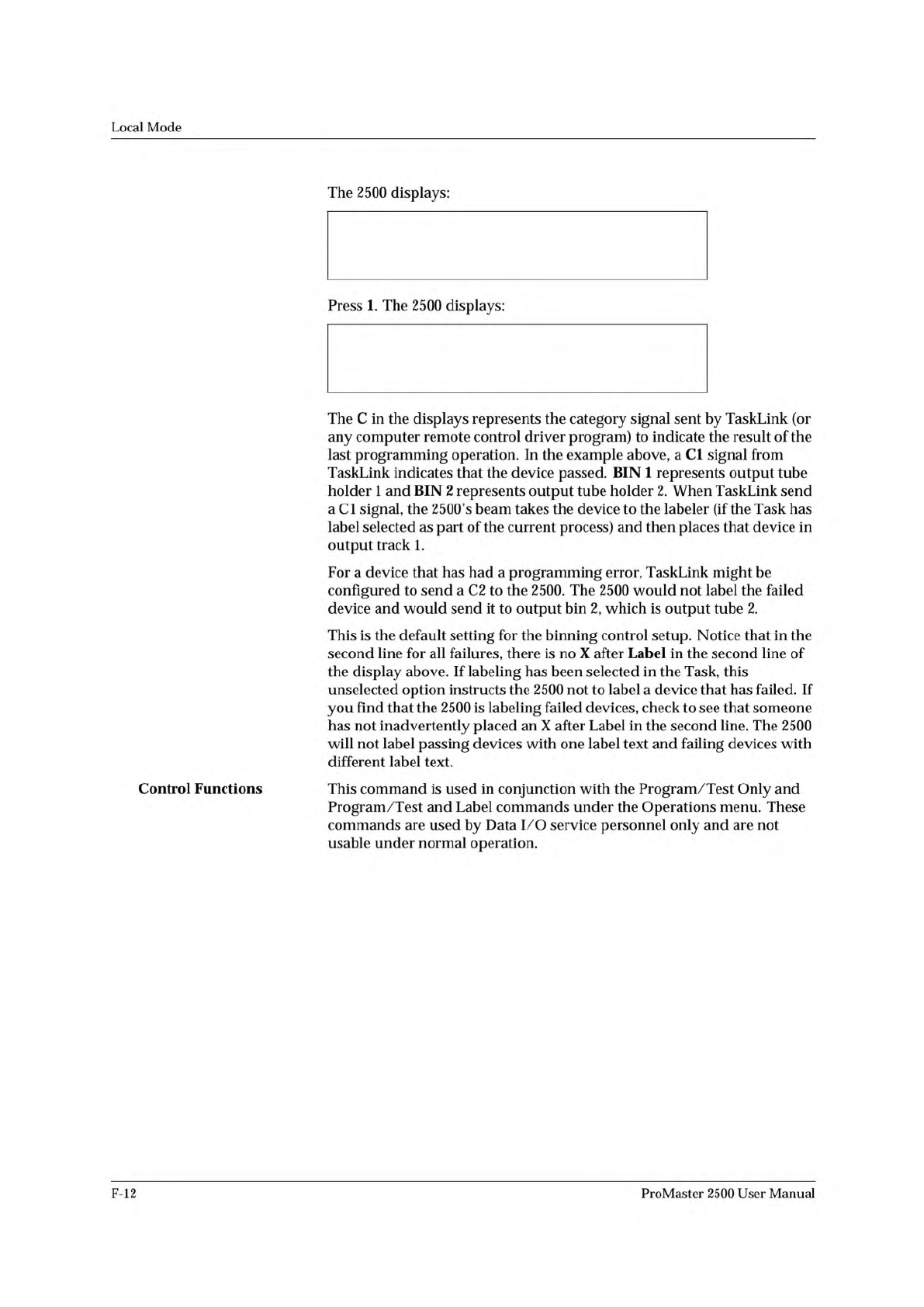
* * * HANDLER SETUP MENU * * *
1 - BINNING
2 - CONTROL FUNCTIONS
3 - SETUP MENU
BIN 1=C1-X C2- C3- C4- C5- LABEL-X
BIN 2=C1- C2-X C3-X C4-X C5-X LABEL-
Local
Mode
Control
Functions
The
2500
displays:
Press
1.
The
2500
displays:
The
C
in
the
displays
represents
the
category
signal
sent
by
TaskLink
(or
any
computer
remote
control
driver
program)
to
indicate
the
result
of
the
last
programming
operation.
In
the
example
above,
a
Cl
signal
from
TaskLink
indicates
that
the
device
passed.
BIN
1
represents
output
tube
holder
1
and
BIN
2
represents
output
tube
holder
2.
When
TaskLink
send
a
Cl
signal,
the
2500's
beam
takes
the
device
to
the
labeler
(if
the
Task
has
label
selected
as
part
of
the
current
process)
and
then
places
that
device
in
output
track
1.
For
a
device
that
has
had
a
programming
error,
TaskLink
might
be
configured
to
send
a
C2
to
the
2500.
The
2500
would
not
label
the
failed
device
and
would
send
it
to
output
bin
2,
which
is
output
tube
2.
This
is
the
default
setting
for
the
binning
control
setup.
Notice
that
in
the
second
line
for
all
failures,
there
is
no
X
after
Label
in
the
second
line
of
the
display
above.
If
labeling
has
been
selected
in
the
Task,
this
unselected
option
instructs
the
2500
not
to
label
a
device
that
has
failed.
If
you
find
that
the
2500
is
labeling
failed
devices,
check
to
see
that
someone
has
not
inadvertently
placed
an
X
after
Label
in
the
second
line.
The
2500
will
not
label
passing
devices
with
one
label
text
and
failing
devices
with
different
label
text.
This
command
is
used
in
conjunction
with
the
Program
/Test
Only
and
Program
/Test
and
Label
commands
under
the
Operations
menu.
These
commands
are
used
by
Data
I/O
service
personnel
only
and
are
not
usable
under
normal
operation.
F-12
ProMaster
2500
User
Manual
A
Absolute
addressing,
3-17
Adapter,
air
connection,
2-4
ADC
optic
adjusting
value,
5-34,
B-2
adjusting,
dot
matrix
printer,
5-34
adjusting,
thermal
printer,
5-35
label
calibration,
5-7
positioning,
5-7
roller
assembly,
5-15,
5-17
super
optic
collector,
A-5
Adjusting
ADC
optic,
dot
matrix
printer,
5-34
ADC
optic,
thermal
printer,
5-35
ADC
value,
5-34,
B-2
dot
matrix
print
head
gap,
5-24
dot
split,
2-26
label
placement,
2-25,
5-25
label
print
position,
5-25
label
print
position,
thermal
printer,
5-26
labels,
5-25
print
intensity,
thermal
printer,
2-29
print
quality,
dot
matrix
printer,
2-22
thermal
printer,
5-27
track,
5-64
track
air,
4-38
track
width,
4-12
Air
handler
input,
4-17
input
requirements,
2-2
Air
filter,
external,
2-5
Air
flow,
system,
5-9
Air
gauges,
setting,
2-7,
4-17
Air
input,
pressure,
4-17
Air
line
adapter,
2-4
connection,
2-5
disconnecting,
2-6
Air
pressure
adjusting,
2-7
adjustment
knobs,
1-4
recommended
settings,
2-5
Alarm,
audible,
setting,
F-9
Algorithm-specific
error
message,
6-2
Aligning
device
to
DIP/SOIC/32-pin
PLCC
module,
4-31
to
PLCC
module,
4-27
Anti-backlash
nut,
replacement,
7-24
Antistatic
precautions,
4-4
Antistatic
wrist
strap,
5-50
Application
plate,
checking
the
height,
2-9
Attachment,
8-pin
150
mil
SOIC
device,
4-14
Audible
alarm
about,
2-21
setting,
F-9
Automatic
RAM
fill
command,
3-18
Auto-Select,
3-11
ProMaster
2500
User
Manual
Index-
1