2500_Users_Manual-.pdf - 第425页
A Absolute addressing, 3-17 Adapter, air connection, 2-4 ADC optic adjusting value, 5-34, B-2 adjusting, dot matrix printer, 5-34 adjusting, thermal printer, 5-35 label calibration, 5-7 positioning, 5-7 roller assembly, …
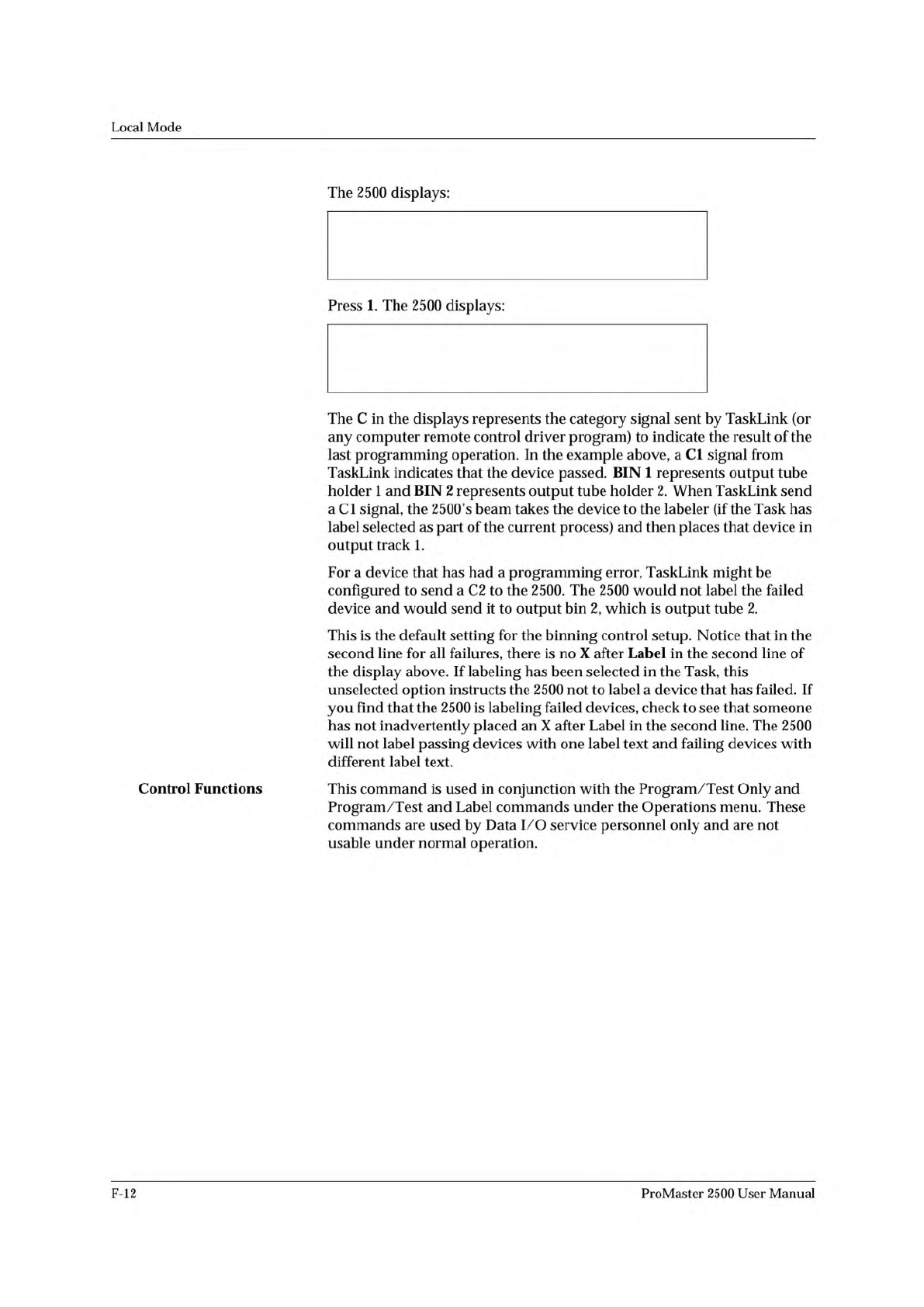
* * * HANDLER SETUP MENU * * *
1 - BINNING
2 - CONTROL FUNCTIONS
3 - SETUP MENU
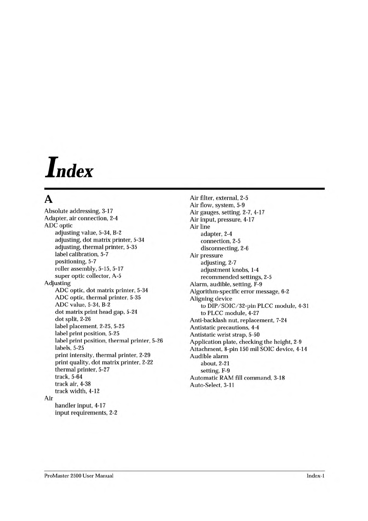
BIN 1=C1-X C2- C3- C4- C5- LABEL-X
BIN 2=C1- C2-X C3-X C4-X C5-X LABEL-
Local
Mode
Control
Functions
The
2500
displays:
Press
1.
The
2500
displays:
The
C
in
the
displays
represents
the
category
signal
sent
by
TaskLink
(or
any
computer
remote
control
driver
program)
to
indicate
the
result
of
the
last
programming
operation.
In
the
example
above,
a
Cl
signal
from
TaskLink
indicates
that
the
device
passed.
BIN
1
represents
output
tube
holder
1
and
BIN
2
represents
output
tube
holder
2.
When
TaskLink
send
a
Cl
signal,
the
2500's
beam
takes
the
device
to
the
labeler
(if
the
Task
has
label
selected
as
part
of
the
current
process)
and
then
places
that
device
in
output
track
1.
For
a
device
that
has
had
a
programming
error,
TaskLink
might
be
configured
to
send
a
C2
to
the
2500.
The
2500
would
not
label
the
failed
device
and
would
send
it
to
output
bin
2,
which
is
output
tube
2.
This
is
the
default
setting
for
the
binning
control
setup.
Notice
that
in
the
second
line
for
all
failures,
there
is
no
X
after
Label
in
the
second
line
of
the
display
above.
If
labeling
has
been
selected
in
the
Task,
this
unselected
option
instructs
the
2500
not
to
label
a
device
that
has
failed.
If
you
find
that
the
2500
is
labeling
failed
devices,
check
to
see
that
someone
has
not
inadvertently
placed
an
X
after
Label
in
the
second
line.
The
2500
will
not
label
passing
devices
with
one
label
text
and
failing
devices
with
different
label
text.
This
command
is
used
in
conjunction
with
the
Program
/Test
Only
and
Program
/Test
and
Label
commands
under
the
Operations
menu.
These
commands
are
used
by
Data
I/O
service
personnel
only
and
are
not
usable
under
normal
operation.
F-12
ProMaster
2500
User
Manual
A
Absolute
addressing,
3-17
Adapter,
air
connection,
2-4
ADC
optic
adjusting
value,
5-34,
B-2
adjusting,
dot
matrix
printer,
5-34
adjusting,
thermal
printer,
5-35
label
calibration,
5-7
positioning,
5-7
roller
assembly,
5-15,
5-17
super
optic
collector,
A-5
Adjusting
ADC
optic,
dot
matrix
printer,
5-34
ADC
optic,
thermal
printer,
5-35
ADC
value,
5-34,
B-2
dot
matrix
print
head
gap,
5-24
dot
split,
2-26
label
placement,
2-25,
5-25
label
print
position,
5-25
label
print
position,
thermal
printer,
5-26
labels,
5-25
print
intensity,
thermal
printer,
2-29
print
quality,
dot
matrix
printer,
2-22
thermal
printer,
5-27
track,
5-64
track
air,
4-38
track
width,
4-12
Air
handler
input,
4-17
input
requirements,
2-2
Air
filter,
external,
2-5
Air
flow,
system,
5-9
Air
gauges,
setting,
2-7,
4-17
Air
input,
pressure,
4-17
Air
line
adapter,
2-4
connection,
2-5
disconnecting,
2-6
Air
pressure
adjusting,
2-7
adjustment
knobs,
1-4
recommended
settings,
2-5
Alarm,
audible,
setting,
F-9
Algorithm-specific
error
message,
6-2
Aligning
device
to
DIP/SOIC/32-pin
PLCC
module,
4-31
to
PLCC
module,
4-27
Anti-backlash
nut,
replacement,
7-24
Antistatic
precautions,
4-4
Antistatic
wrist
strap,
5-50
Application
plate,
checking
the
height,
2-9
Attachment,
8-pin
150
mil
SOIC
device,
4-14
Audible
alarm
about,
2-21
setting,
F-9
Automatic
RAM
fill
command,
3-18
Auto-Select,
3-11
ProMaster
2500
User
Manual
Index-
1
Index
B
Baud
rate
changing
2500
ports,
F-9
default,
E-2
setting
on
2500,
2-21
Beam
aligning,
4-27
lead
screw
lubrication,
5-62
stall
and
motor
speed,
B-3
stalling
described,
5-8
stalls,
5-22
theory
of
operation,
5-8
Beam
gasket
replacement,
7-25
Beam
head
rotation
motor
replacement,
7-14
Beam
optic
malfunction
message,
6-2
Beam
traverse
motor
replacement,
7-14
Bearing
plate,
checking
the
height,
2-9,
5-26
Blank
check,
3-8,
5-5,
6-3
Board
pin
driver,
5-20
power
supply,
5-19
relay,
5-19
Bulletin
Board
Service,
xx
Button
CAL,
1-10
E-stop,
4
START,
1-10
c
Calibrating
labels
dot
matrix
labeler,
2-11
theory
of
operation,
5-15,
5-17
thermal
printer,
2-14
Calibration
label
detection
optic,
4-19
PE,
5-20
setting,
label,
5-25
value,
label,
B-4
Capacitor
configuration
error
message,
6-2
Categories
see
Handler
sorting
Category
X
bin
not
available
message,
6-2
Changing
your
address,
xxii
Characters
per
inch
dot
matrix
printer,
5-15
thermal
printer,
5-17
Chart,
chuck
selection,
4-16
Checkboxes,
1-14
Checking
communication,
TaskLink,
2-19
Chuck
about,
1-9
installing,
2-8,
4-16
replacing
the
tip,
4-17
selection
chart,
2-8,
4-16,
4-17
theory
of
operation,
5-8
tips,
cleaning,
5-56
Cleaning
application
plate,
5-57
beam,
5-61
chuck
tips,
5-56
DIP
modules,
5-56
label
path,
dot
matrix
printer,
5-57
optic
holes,
5-56
periodic,
5-56
pinch
rollers,
5-57
programming
module,
5-57
SOIC
modules,
5-56
SPA
block,
5-56
2500
exterior,
5-56
Command
set,
remote
mode,
E-4
—
E-9
Communications
test,
5-49
Compensated
vector
test,
3-13
Computer
remote
control
command
set,
handler,
E-2
default
settings,
E-18
firmware
key,
B-2
halting
an
operation,
E-17
overview,
E-l
programmer
electronics
summary,
E-18
programming
electronics
setup,
E-17
Remote
port
setup,
E-2
software
driver,
E-l
standard
vs.
extended
commands,
E-19
Configuration
blocks,
4-8
Configuration
chart,
programming
module,
4-10
Configuring
the
programming
module,
4-8
Connecting
source
air
line,
2-5
2500
to
PC,
2-16
Continuity
test
fail,
5-4
Controller
board
about,
5-19
replacement,
7-20
theory
of
operation,
5-13
Controller
power
supply,
replacement,
7-19
CPI
(Characters
Per
Inch),
5-15
CRC
Error
Codes,
E-22
Creating
a
new
file,
F-7
Creating
label
text,
3-11
Customer
Resource
Center,
phone
number,
1-19
Customer
Support,
xvii
Cycle
parts,
5-42
Index-2
ProMaster
2500
User
Manual