2500_Users_Manual-.pdf - 第44页
2 Installation and Setup For Administra tors This chapter describes how to install and start the ProMaster 2500 and is directed to system administrators. You should be familiar with the information described in Chapter 1…
Introduction
ProMaster
2500
User
Manual
3/97
1-21
2
Installation
and
Setup
For
Administra
tors
This
chapter
describes
how
to
install
and
start
the
ProMaster
2500
and
is
directed
to
system
administrators.
You
should
be
familiar
with
the
information
described
in
Chapter
1
before
performing
the
operations
described
in
this
chapter.
System
operators
should
skip
Chapters
2
and
3
and
read
the
daily
operating
procedures
described
in
Chapter
4.
The
procedures
in
this
chapter
include
connecting
the
RS-
232c
cables,
connecting
the
external
air
line,
installing
and
starting
TaskLink,
installing
the
periodic
system
disk
updates,
and
confirming
that
the
system
is
communicating
and
that
no
errors
were
detected
during
the
powerup
self-test.
The
information
in
this
chapter
is
organized
as
follows:
Before
You
Install
2-2
Unpacking
and
Inspecting
the
2500
2-2
Installing
the
2500
2-4
Connecting
the
PC
and
Installing
TaskLink
2-16
Turning
on
the
2500
2-18
Adjusting
Print
Quality
and
Position
2-22
Updating
the
2500
2-29
ProMaster
2500
User
Manual
2-1
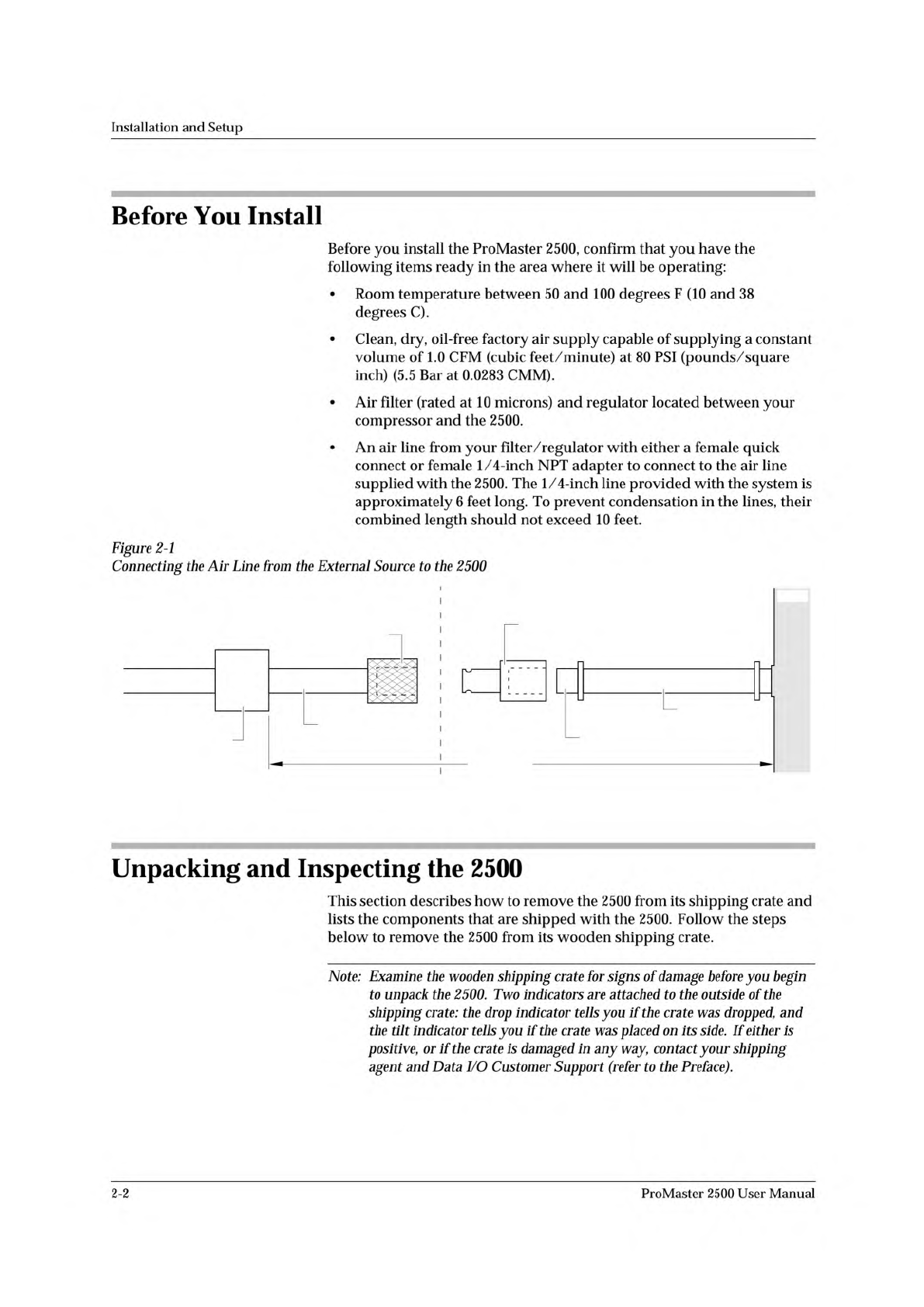
INPUT AIR
LINE (6 ft.)
ADAPTER
MALE QUICK CONNECT
(With female 1/4 NPT)
FEMALE QUICK CONNECT
(Knurled Sleeve)
SOURCE AIR
LINE (4 ft. max)
FILTER/REGULATOR
TO EXTERNAL
AIR SOURCE
10 FT MAX
SUPPLIED BY CUSTOMER DELIVERED WITH PROMASTER
1761-1
2500
Installation
and
Setup
Before
You
Install
Before
you
install
the
ProMaster
2500,
confirm
that
you
have
the
following
items
ready
in
the
area
where
it
will
be
operating:
•
Room
temperature
between
50
and
100
degrees
F
(10
and
38
degrees
C).
•
Clean,
dry,
oil-free
factory
air
supply
capable
of
supplying
a
constant
volume
of
1.0
CFM
(cubic
feet/minute)
at
80
PSI
(pounds/square
inch)
(5.5
Bar
at
0.0283
CMM).
•
Air
filter
(rated
at
10
microns)
and
regulator
located
between
your
compressor
and
the
2500.
•
An
air
line
from
your
filter/regulator
with
either
a
female
quick
connect
or
female
1/4-inch
NPT
adapter
to
connect
to
the
air
line
supplied
with
the
2500.
The
1/4-inch
line
provided
with
the
system
is
approximately
6
feet
long.
To
prevent
condensation
in
the
lines,
their
combined
length
should
not
exceed
10
feet.
Figure
2-1
Connecting
the
Air
Line
from
the
External
Source
to
the
2500
Unpacking
and
Inspecting
the
2500
This
section
describes
how
to
remove
the
2500
from
its
shipping
crate
and
lists
the
components
that
are
shipped
with
the
2500.
Follow
the
steps
below
to
remove
the
2500
from
its
wooden
shipping
crate.
Note:
Examine
the
wooden
shipping
crate
for
signs
of
damage
before
you
begin
to
unpack
the
2500.
Two
indicators
are
attached
to
the
outside
of
the
shipping
crate:
the
drop
indicator
tells
you
if
the
crate
was
dropped,
and
the
indicator
tells
you
if
the
crate
was
placed
on
its
side.
If
either
Is
positive,
or
if
the
crate
is
damaged
加
any
way,
contact
your
shipping
agent
and
Data
I/O
Customer
Support
(refer
to
the
Preface).
2-2
ProMaster
2500
User
Manual