2500_Users_Manual-.pdf - 第46页
2306-1 FRONT REAR TOP PALET Installation and Setup Figure 2-2 The 2500 Shipping Crate 1. Remove the eight screws (two on each vertical panel) that hold together the panels of the shipping crate (see Figure 2-2). 2. Caref…
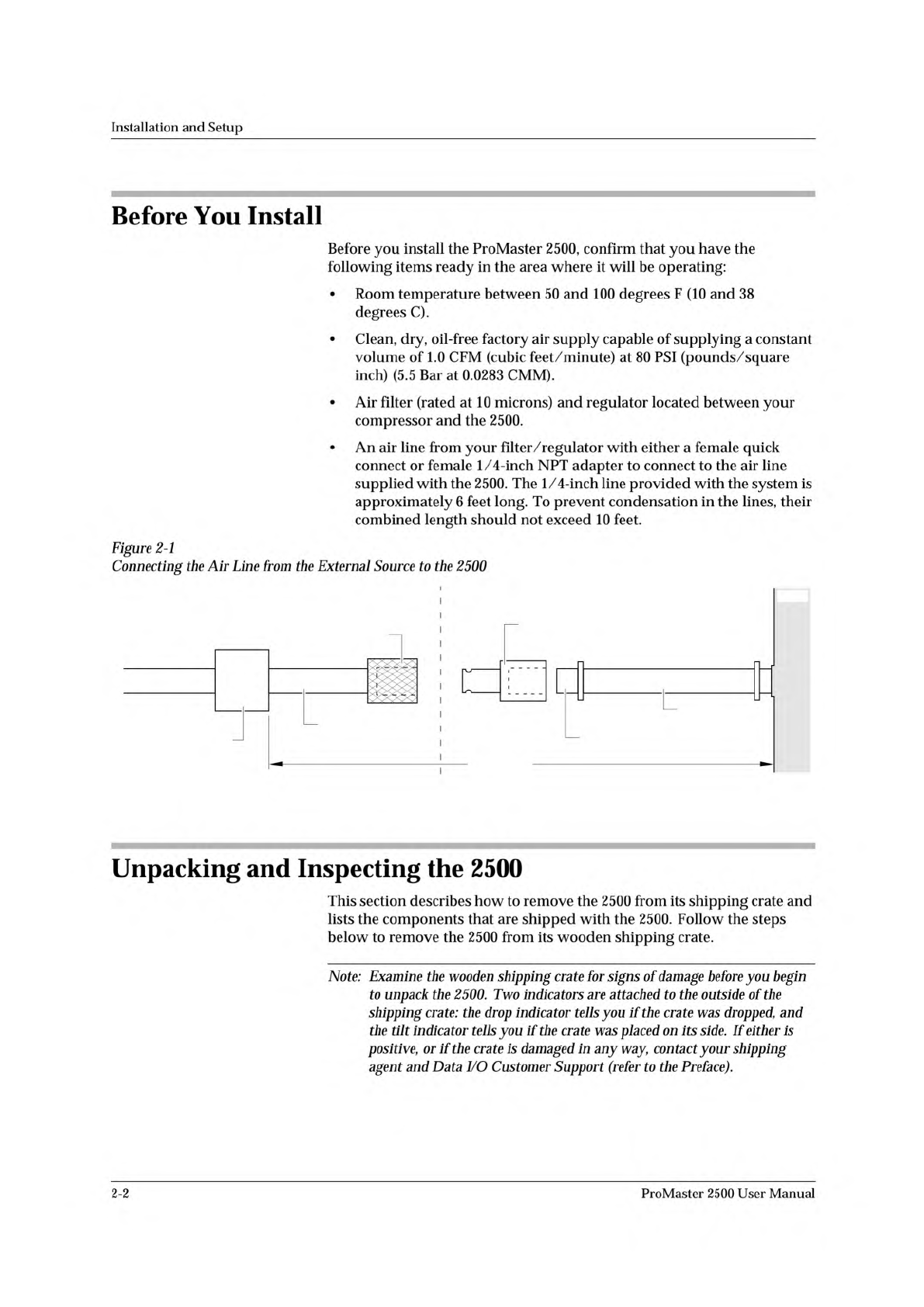
INPUT AIR
LINE (6 ft.)
ADAPTER
MALE QUICK CONNECT
(With female 1/4 NPT)
FEMALE QUICK CONNECT
(Knurled Sleeve)
SOURCE AIR
LINE (4 ft. max)
FILTER/REGULATOR
TO EXTERNAL
AIR SOURCE
10 FT MAX
SUPPLIED BY CUSTOMER DELIVERED WITH PROMASTER
1761-1
2500
Installation
and
Setup
Before
You
Install
Before
you
install
the
ProMaster
2500,
confirm
that
you
have
the
following
items
ready
in
the
area
where
it
will
be
operating:
•
Room
temperature
between
50
and
100
degrees
F
(10
and
38
degrees
C).
•
Clean,
dry,
oil-free
factory
air
supply
capable
of
supplying
a
constant
volume
of
1.0
CFM
(cubic
feet/minute)
at
80
PSI
(pounds/square
inch)
(5.5
Bar
at
0.0283
CMM).
•
Air
filter
(rated
at
10
microns)
and
regulator
located
between
your
compressor
and
the
2500.
•
An
air
line
from
your
filter/regulator
with
either
a
female
quick
connect
or
female
1/4-inch
NPT
adapter
to
connect
to
the
air
line
supplied
with
the
2500.
The
1/4-inch
line
provided
with
the
system
is
approximately
6
feet
long.
To
prevent
condensation
in
the
lines,
their
combined
length
should
not
exceed
10
feet.
Figure
2-1
Connecting
the
Air
Line
from
the
External
Source
to
the
2500
Unpacking
and
Inspecting
the
2500
This
section
describes
how
to
remove
the
2500
from
its
shipping
crate
and
lists
the
components
that
are
shipped
with
the
2500.
Follow
the
steps
below
to
remove
the
2500
from
its
wooden
shipping
crate.
Note:
Examine
the
wooden
shipping
crate
for
signs
of
damage
before
you
begin
to
unpack
the
2500.
Two
indicators
are
attached
to
the
outside
of
the
shipping
crate:
the
drop
indicator
tells
you
if
the
crate
was
dropped,
and
the
indicator
tells
you
if
the
crate
was
placed
on
its
side.
If
either
Is
positive,
or
if
the
crate
is
damaged
加
any
way,
contact
your
shipping
agent
and
Data
I/O
Customer
Support
(refer
to
the
Preface).
2-2
ProMaster
2500
User
Manual
2306-1
FRONT
REAR
TOP
PALET
Installation
and
Setup
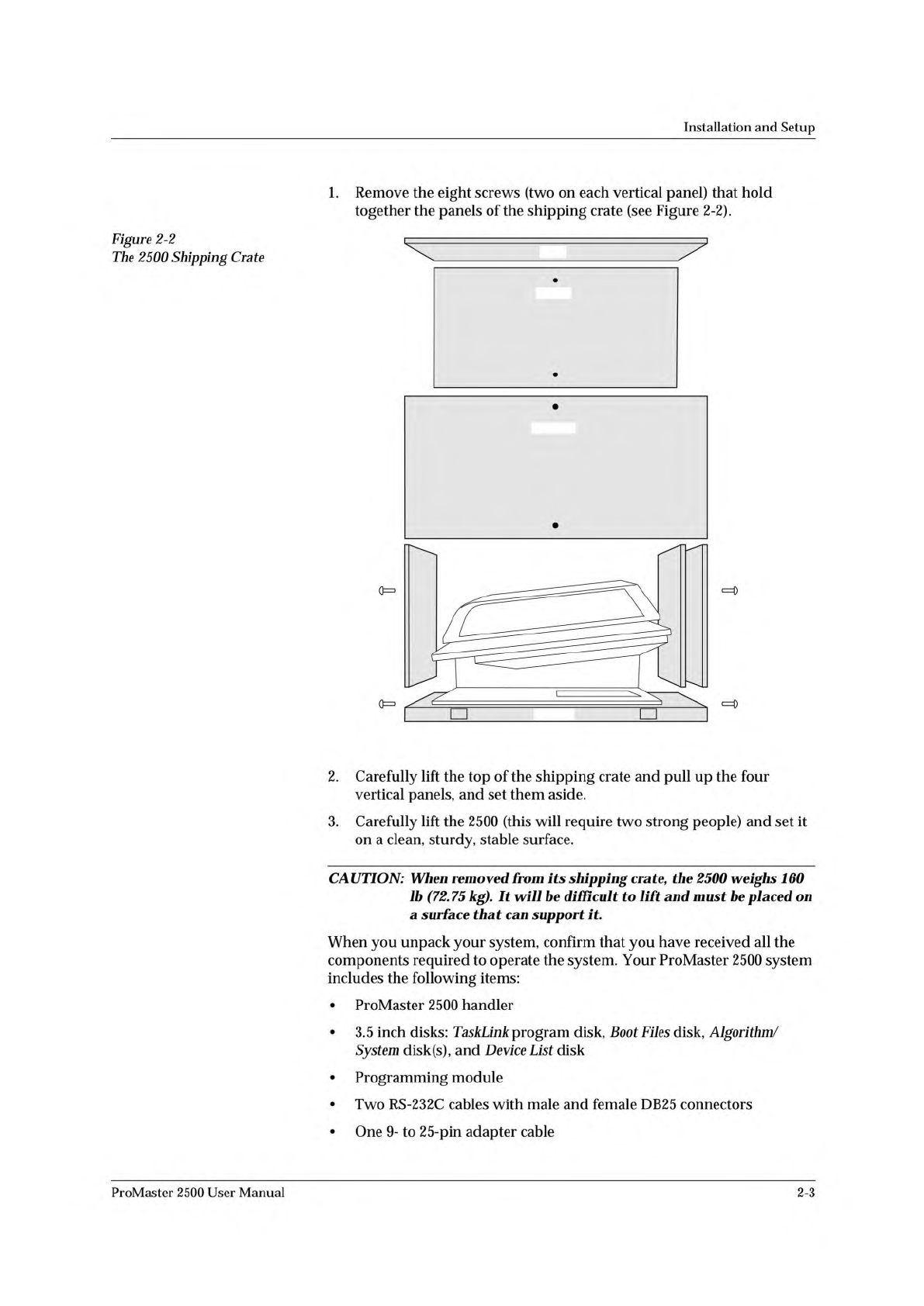
Figure
2-2
The
2500
Shipping
Crate
1.
Remove
the
eight
screws
(two
on
each
vertical
panel)
that
hold
together
the
panels
of
the
shipping
crate
(see
Figure
2-2).
2.
Carefully
lift
the
top
of
the
shipping
crate
and
pull
up
the
four
vertical
panels,
and
set
them
aside.
3.
Carefully
lift
the
2500
(this
will
require
two
strong
people)
and
set
it
on
a
clean,
sturdy,
stable
surface.
CAUTION:
When
removed
from
its
shipping
crate
f
the
2500
weighs
160
lb
(72.
75
kg).
It
be
difficult
to
lift
and
must
be
placed
on
a
surface
that
can
support
it.
When
you
unpack
your
system,
confirm
that
you
have
received
all
the
components
required
to
operate
the
system.
Your
ProMaster
2500
system
includes
the
following
items:
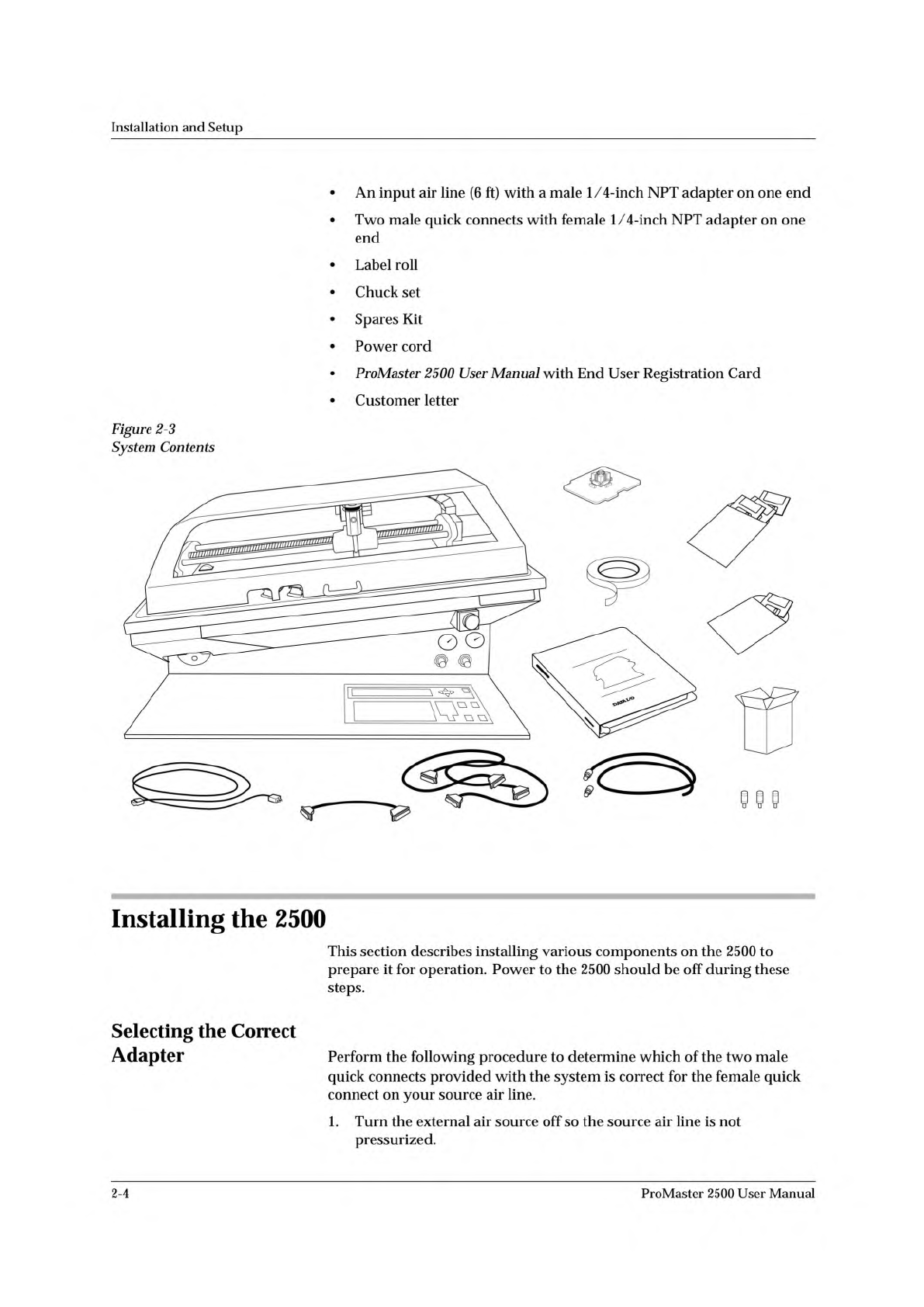
•
ProMaster
2500
handler
•
3.5
inch
disks:
TaskLink
program
disk,
Boot
Files
disk,
Algorithm/
System
disk(s),
and
Device
List
disk
•
Programming
module
•
Two
RS-
232c
cables
with
male
and
female
DB25
connectors
ProMaster
2500
User
Manual
•
One
9-
to
25-pin
adapter
cable
2-3
PROMASTER 2500
DISKS
POWER CORD
USER
MANUAL
1763-3
RS-232 CABLE (2)
P
r
o
M
a
s
t
e
r
2
5
0
0
TASKLINK
DISK
LABEL
ROLL
1/4" INPUT AIR LINE
(With 2 adapters)
PROGRAMMING
MODULE
9 - 25 PIN
CABLE
SPARES KIT
CHUCK SET
Installation
and
Setup
•
An
input
air
line
(6
ft)
with
a
male
1/4-inch
NPT
adapter
on
one
end
•
Two
male
quick
connects
with
female
1/
4-inch
NPT
adapter
on
one
end
•
Label
roll
•
Chuck
set
•
Spares
Kit
•
Power
cord
•
ProMaster
2500
User
Manual
with
End
User
Registration
Card
•
Customer
letter
Figure
2-3
System
Contents
Installing
the
2500
This
section
describes
installing
various
components
on
the
2500
to
prepare
it
for
operation.
Power
to
the
2500
should
be
off
during
these
steps.
Selecting
the
Correct
Adapter
Perform
the
following
procedure
to
determine
which
of
the
two
male
quick
connects
provided
with
the
system
is
correct
for
the
female
quick
connect
on
your
source
air
line.
1.
Turn
the
external
air
source
off
so
the
source
air
line
is
not
pressurized.
2-4
ProMaster
2500
User
Manual