2500_Users_Manual-.pdf - 第50页
L O W P R E S S U R E 2 0 - 5 0 P S I H I G H P R E S S U R E 6 5 - 8 5 P S I A J S SHIFT B K T DEL C L U D M V E N W F O X SHIFT G P Y H Q Z I R ENT ER 1 4 7 2 5 8 3 6 9 0 LO WER CASE RESE T STO P CAL STA RT ON 176 4-4 …
AIR LINE
MALE QUICK
CONNECT
FEMALE QUICK CONNECT
SOURCE AIR LINE
FILTER/REGULATOR
TO EXTERNAL
AIR SOURCE
SUPPLIED BY CUSTOMER DELIVERED WITH PROMASTER
1956-1
COLLAR
2500
SIDE VIEW
Installation
and
Setup
5.
The
2500,s
high
and
low
air
pressure
gauges
will
immediately
display
their
current
settings.
Adjust
these
by
performing
the
procedure
on
page
2-7.
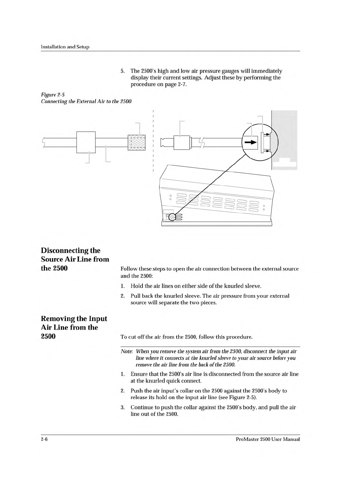
Figure
2-5
Connecting
the
External
Air
to
the
2500
Disconnecting
the
Source
Air
Line
from
the
2500
Follow
these
steps
to
open
the
air
connection
between
the
external
source
and
the
2500:
1.
Hold
the
air
lines
on
either
side
of
the
knurled
sleeve.
2.
Pull
back
the
knurled
sleeve.
The
air
pressure
from
your
external
source
will
separate
the
two
pieces.
Removing
the
Input
Air
Line
from
the
2500
To
cut
off
the
air
from
the
2500,
follow
this
procedure.
Note:
When
you
remove
the
system
air
from
the
2500,
disconnect
the
input
air
line
where
it
connects
at
the
knurled
sleeve
to
your
air
source
before
you
remove
the
air
line
from
the
back
of
the
2500.
1.
Ensure
that
the
2500's
air
line
is
disconnected
from
the
source
air
line
at
the
knurled
quick
connect.
2.
Push
the
air
inpufs
collar
on
the
2500
against
the
2500's
body
to
release
its
hold
on
the
input
air
line
(see
Figure
2-5).
3.
Continue
to
push
the
collar
against
the
2500's
body,
and
pull
the
air
line
out
of
the
2500.
2-6
ProMaster
2500
User
Manual
L
O
W
P
R
E
S
S
U
R
E
2
0
-
5
0
P
S
I
H
I
G
H
P
R
E
S
S
U
R
E
6
5
-
8
5
P
S
I
A
J
S
SHIFT
B
K
T
DEL
C
L
U
D
M
V
E
N
W
F
O
X
SHIFT
G
P
Y
H
Q
Z
I
R
ENTER
1
4
7
2
5
8
3
6
9
0
LOWER
CASE
RESET
STOP
CAL
START
ON
1764-4
HIGH PRESSURE
ADJUSTMENT KNOB
LOW PRESSURE
ADJUSTMENT KNOB
Installation
and
Setup
The
line
should
come
out
easily,
without
any
resistance.
If
it
is
difficult
to
remove,
make
sure
that
the
collar
is
fully
depressed
against
the
2500's
body
before
pulling
on
the
air
line
(see
Figure
2-5).
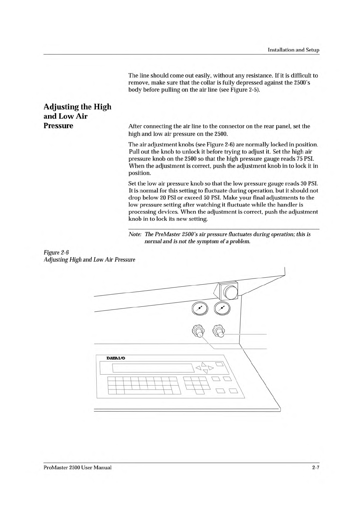
Ac^usting
the
High
and
Low
Air
Pressure
After
connecting
the
air
line
to
the
connector
on
the
rear
panel,
set
the
high
and
low
air
pressure
on
the
2500.
The
air
adjustment
knobs
(see
Figure
2-6)
are
normally
locked
in
position.
Pull
out
the
knob
to
unlock
it
before
trying
to
adjust
it.
Set
the
high
air
pressure
knob
on
the
2500
so
that
the
high
pressure
gauge
reads
75
PSI.
When
the
adjustment
is
correct,
push
the
adjustment
knob
in
to
lock
it
in
position.
Set
the
low
air
pressure
knob
so
that
the
low
pressure
gauge
reads
30
PSI.
It
is
normal
for
this
setting
to
fluctuate
during
operation,
but
it
should
not
drop
below
20
PSI
or
exceed
50
PSI.
Make
your
final
adjustments
to
the
low
pressure
setting
after
watching
it
fluctuate
while
the
handler
is
processing
devices.
When
the
adjustment
is
correct,
push
the
adjustment
knob
in
to
lock
its
new
setting.
Note:
The
ProMaster
2500
's
air
pressure
fluctuates
during
operation;
this
is
normal
and
is
not
the
symptom
of
a
problem.
Figure
2-6
Adjusting
High
and
Low
Air
Pressure
ProMaster
2500
User
Manual
2-7
DEVICE
TYPE
PLCC
DIP
L M N
20-PIN
28-PIN
32-PIN
44-PIN
52-PIN
68-PIN
84-PIN
300 mil
600 mil
1850-3
Recommended
Alternate
SOIC 150 mil
220 mil
300 mil
330 mil
420 mil
500 mil
K
CHUCK
ProMaster 2500
Installation
and
Setup
Installing
and
Removing
Chucks
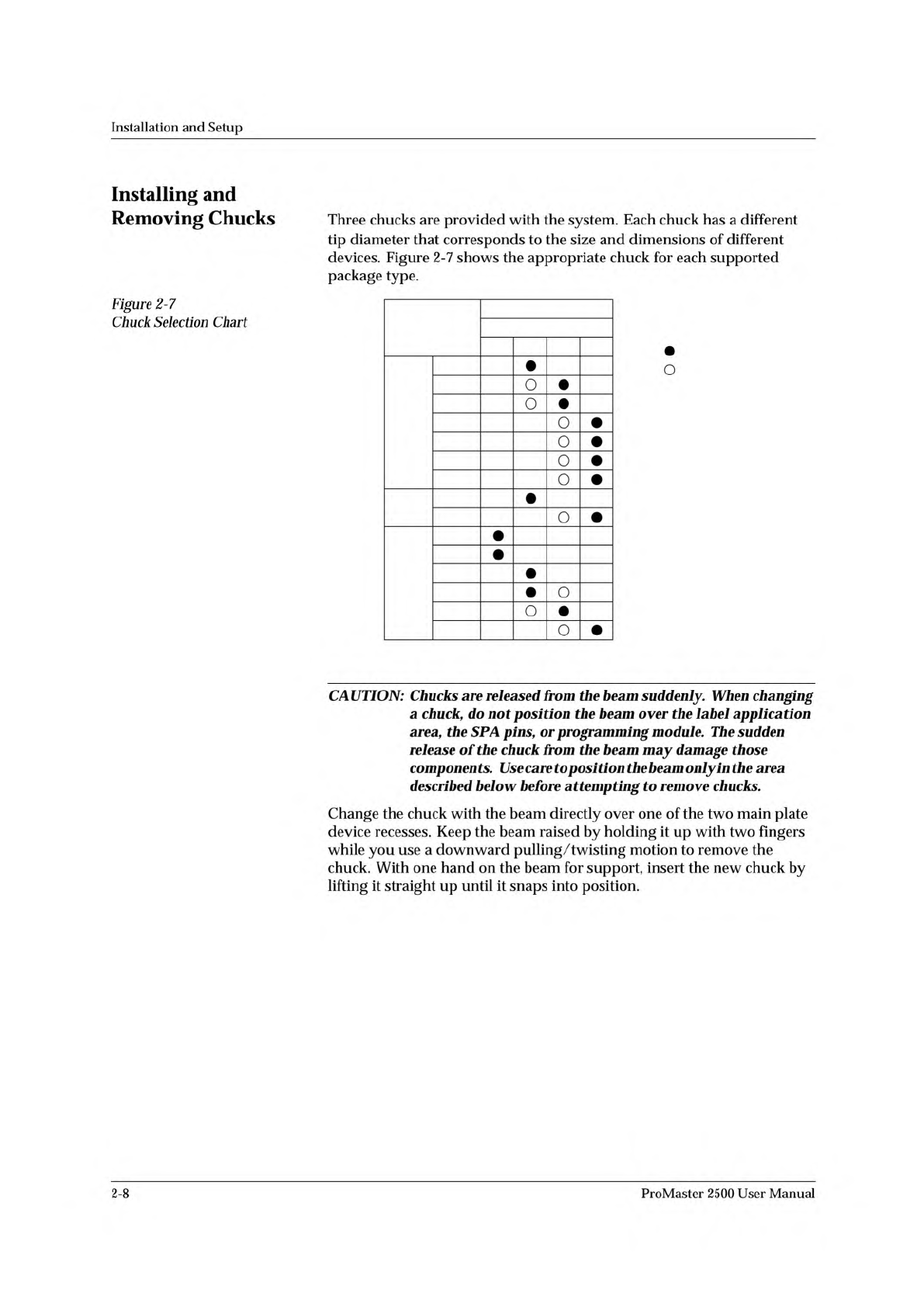
Figure
2-7
Chuck
Selection
Chart
Three
chucks
are
provided
with
the
system.
Each
chuck
has
a
different
tip
diameter
that
corresponds
to
the
size
and
dimensions
of
different
devices.
Figure
2-7
shows
the
appropriate
chuck
for
each
supported
package
type.
O
CAUTION:
Chucks
are
released
from
the
beam
suddenly.
When
changing
a
chuck,
do
not
position
the
beam
over
the
label
application
area,
the
SPA
pig
or
programming
module.
The
sudden
release
of
the
chuck
from
the
beam
may
damage
those
components.
Use
care
to
posi
tion
the
beam
only
in
the
area
described
below
before
attempting
to
remove
chucks.
Change
the
chuck
with
the
beam
directly
over
one
of
the
two
main
plate
device
recesses.
Keep
the
beam
raised
by
holding
it
up
with
two
fingers
while
you
use
a
downward
pulling/twisting
motion
to
remove
the
chuck.
With
one
hand
on
the
beam
for
support,
insert
the
new
chuck
by
lifting
it
straight
up
until
it
snaps
into
position.
2-8
ProMaster
2500
User
Manual