2500_Users_Manual-.pdf - 第59页
Installation and Setup 5. Guide the pinch roller back into its operating position against the drive roller. 6. Use the tape supplied on the end of the leader (or a DIP label) to attach the leader to the take-up cardboard…
2304-2
PRINT HEAD (Retracted position)
RIBBON ALIGNMENT ROLLER 2
RIBBON ALIGNMENT
ROLLER 1
RIBBON DETECT OPTIC
RIBBON ROLL
RIBBON PINCH
ROLLER
RIBBON DRIVE ROLLER
PLATEN
RIBBON TAKE-UP ROLL
APPLICATION AREA
1 2 3
4
5 6
8
Installation
and
Setup
Installing
a
New
Ribbon
Each
new
ribbon
roll
has
a
long
leader
to
thread
through
the
labeler.
Follow
the
procedure
below
to
install
the
new
ribbon
(refer
to
Figure
2-12).
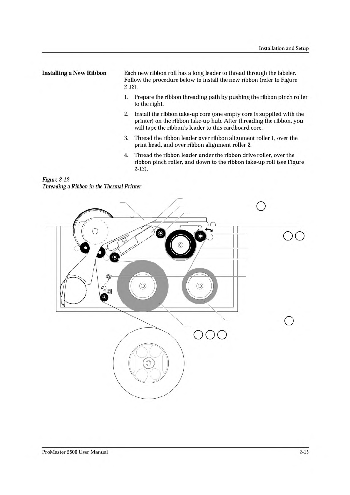
1.
Prepare
the
ribbon
threading
path
by
pushing
the
ribbon
pinch
roller
to
the
right.
2.
Install
the
ribbon
take-up
core
(one
empty
core
is
supplied
with
the
printer)
on
the
ribbon
take-up
hub.
After
threading
the
ribbon,
you
will
tape
the
ribbon's
leader
to
this
cardboard
core.
3.
Thread
the
ribbon
leader
over
ribbon
alignment
roller
1,
over
the
print
head,
and
over
ribbon
alignment
roller
2.
4.
Thread
the
ribbon
leader
under
the
ribbon
drive
roller,
over
the
ribbon
pinch
roller,
and
down
to
the
ribbon
take-up
roll
(see
Figure
2-12).
°
Figure
2-12
Threading
a
Ribbon
in
the
Thermal
Printer
ProMaster
2500
User
Manual
2-15
Installation
and
Setup
5.
Guide
the
pinch
roller
back
into
its
operating
position
against
the
drive
roller.
6.
Use
the
tape
supplied
on
the
end
of
the
leader
(or
a
DIP
label)
to
attach
the
leader
to
the
take-up
cardboard
core.
7.
When
you
install
a
new
ribbon,
remove
the
old
ribbon's
cardboard
core
and
install
it
on
the
take-up
hub
as
the
new
ribbon
take-up
core.
8.
Turn
the
ribbon
take-up
roll
counterclockwise
to
advance
the
ribbon
until
it
(not
the
leader)
is
between
the
print
head
and
the
platen.
Repairing
a
Torn
Ribbon
Under
normal
circumstances
you
should
not
have
a
problem
with
the
ribbon
tearing.
If
it
does
tear,
follow
the
procedure
below
to
repair
it.
1.
2.
Cut
the
end
of
the
ribbon
to
remove
the
tear
and
create
a
straight
end.
Cut
about
16
inches
(40
cm)
of
old
label
liner
(hanging
from
the
label
drive
roller)
to
use
as
ribbon
leader.
3.
Line
up
the
end
of
the
ribbon
with
the
end
of
the
liner
and
tape
the
two
ends
together
(a
DIP
label
can
also
be
used
as
a
tape
splice).
4.
5.
Turn
the
splice
over
and
tape
the
other
side.
Wrap
the
liner
around
the
ribbon
roll
once,
and
then
follow
the
instructions
for
installing
a
new
ribbon.
If
the
ribbon
begins
to
slide
off
the
roll
while
you
are
threading,
place
a
large
label
across
the
edge
of
the
ribbon
roll
to
stop
the
unraveling.
Remove
this
label
when
you
have
finished
threading
and
before
you
start
processing
devices.
Connecting
the
PC
and
Installing
TaskLink
Before
you
start
creating
Tasks
using
TaskLink,
you
will
need
to:
1.
Connect
the
RS-
232c
cables
between
the
PC
and
the
2500.
2.
Install
TaskLink
on
the
PC.
3.
Start
the
program.
Connecting
the
PC
Connect
the
2500
to
the
two
PC
COM
ports
using
the
cables
provided
with
the
system.
The
cables
are
the
same
type
and
can
be
used
on
either
port
on
the
2500.
1.
Connect
one
of
the
serial
cables
to
the
COM1
serial
port
on
the
back
of
your
PC.
TaskLink
uses
COM1
as
the
default
programmer
port.
Note:
If
your
PC
has
a
9-pin
connector,
use
9-pin
adapter
included
with
the
system
to
connect
the
data
cable
to
your
PC.
2.
Connect
the
other
end
of
the
COM1
cable
to
the
connector
labeled
Programmer
Port
on
the
back
of
the
2500.
2-16
ProMaster
2500
User
Manual
↵
Installation
and
Setup
3.
Connect
one
end
of
the
second
serial
cable
to
the
COM2
serial
port
on
the
back
of
your
PC.
TaskLink
uses
COM2
as
the
default
Remote
port.
It
does
not
use
any
other
COM
ports
other
than
1
and
2.
If
you
plan
to
use
a
mouse
with
TaskLink,
it
must
be
a
bus
mouse;
or
you
can
set
a
COM
port
to
3
or
4
and
use
an
interrupt
other
than
IRQ
3
or
4.
4.
Connect
the
other
end
of
this
COM2
cable
to
the
connector
labeled
Remote
RS-232
on
the
back
of
the
2500.
5.
When
you
run
TaskLink,
the
software
configures
the
COM1
and
COM2
ports
on
your
PC
to
match
the
defaults
used
by
TaskLink.
The
system
defaults
for
TaskLink
ports
are:
•
9600
baud
•
8
data
bits
•
No
parity
•
1
stop
bit
Installing
TaskLink
On
the
PC
Install
TaskLink
on
your
PC
by
performing
the
following
steps:
Note:
The
following
instructions
are
for
TaskLink
for
DOS.
If
you
are
using
TaskLink
for
Windows,
refer
to
the
TLFW
Getting
Started
Guide
and
the
online
Help
fbr
installation
and
operation
instructions.
1.
Insert
the
TaskLink
disk
into
the
floppy
disk
drive
on
your
PC.
2.
From
your
hard
disk
prompt,
enter
dnve:install
where
drive
is
the
disk
drive
holding
the
TaskLink
disk.
Your
command
line
might
look
something
like
this:
C:\b:install
3.
Press
.
The
installation
program
will
prompt
you
for
the
information
needed
to
complete
the
installation.
ProMaster
2500
User
Manual
2-17