2500_Users_Manual-.pdf - 第74页
↵ OPTIC TEST - ADC = 200 - VAC = 23 11100000001111101111111100 ENC = 13107 | | | | | U15 REV 1.00 5 10 15 20 25 U43 REV 1.00 1955-2 +5 V -1 2V +1 2V +3 6V +9 0V CR111 CR75 CR99 CR51 CR87 CR63 CR112 CR76 CR100 CR52 CR88 C…
Installation
and
Setup
Installing
a
2500
Firmware
Update
The
2500
firmware
will
be
updated
periodically
to
add
new
operating
features.
The
update
replaces
the
EPROM
in
location
U15
and/or
U43
on
the
handler
controller
board.
CAUTION:
To
avoid
possible
damage
to
the
system
components,
this
procedure
should
be
performed
only
by
a
qualified
service
technician.
Observe
antistatic
precautions
while
performing
this
operation.
Follow
these
steps
to
install
a
firmware
update
to
the
2500.
To
reduce
or
prevent
possible
damage
to
these
static-sensitive
devices
from
ESD,
wear
your
antistatic
wrist
strap
when
performing
this
procedure.
1.
Turn
off
the
2500
and
remove
the
power
cord.
2.
Remove
all
devices
from
the
tracks
and
all
tubes
from
the
tube
holders.
3.
Unscrew
the
two
corner
screws
that
hold
the
main
plate
to
the
2500's
base.
4.
Lift
the
main
plate
to
expose
the
2500's
interior,
and
remove
the
internal
device
shield.
WARNING:
To
prevent
the
hood
or
main
plate
from
accidentally
falling
shut,
be
careful
not
to
jar
the
2500
when
they
are
raised.
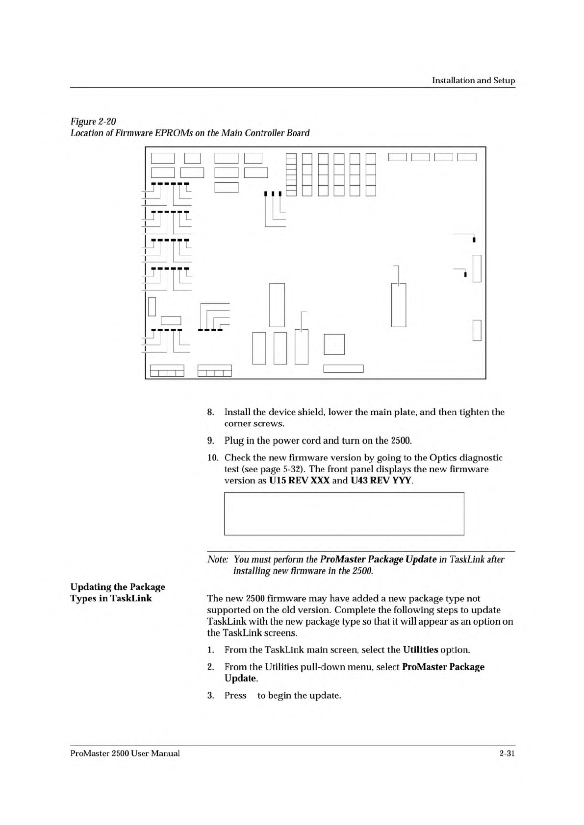
5.
Locate
the
U15/U43
EPROM
on
the
handler
controller
board
(refer
to
the
controller
board
layout
in
Figure
2-20
and
Appendix
C).
6.
Use
an
IC
remover
tool
to
carefully
remove
the
current
DIP
firmware
device
from
its
socket.
7.
Install
the
new
firmware
device
in
the
socket,
being
careful
not
to
bend
any
of
the
device
leads.
Make
sure
that
pin
1
is
properly
oriented.
2-30
ProMaster
2500
User
Manual
↵
OPTIC TEST - ADC = 200 - VAC = 23
11100000001111101111111100 ENC = 13107
| | | | | U15 REV 1.00
5 10 15 20 25 U43 REV 1.00
1955-2
+5V
-12V
+12V
+36V
+90V
CR111
CR75
CR99
CR51
CR87
CR63
CR112
CR76
CR100
CR52
CR88
CR64
CR113
CR77
CR101
CR53
CR89
CR65
CR114
CR78
CR102
CR54
CR90
CR66
+24V
S8
S7
S5
S6
S2
S3
S1
S4
U15
EPROM
U43
EPROM
Installation
and
Setup
Figure
2-20
Location
of
Firmware
EPROMs
on
the
Main
Controller
Board
Updating
the
Package
Types
in
TaskLink
8.
Install
the
device
shield,
lower
the
main
plate,
and
then
tighten
the
corner
screws.
9.
Plug
in
the
power
cord
and
turn
on
the
2500.
10.
Check
the
new
firmware
version
by
going
to
the
Optics
diagnostic
test
(see
page
5-32).
The
front
panel
displays
the
new
firmware
version
as
U15
REV
XXX
and
U43
REV
YYY.
Note:
You
must
perform
the
ProMaster
Package
Update
in
TaskLink
after
installing
new
firmware
in
the
2500.
The
new
2500
firmware
may
have
added
a
new
package
type
not
supported
on
the
old
version.
Complete
the
following
steps
to
update
TaskLink
with
the
new
package
type
so
that
it
will
appear
as
an
option
on
the
TaskLink
screens.
1.
From
the
TaskLink
main
screen,
select
the
Utilities
option.
2.
From
the
Utilities
pull-down
menu,
select
ProMaster
Package
Update.
3.
Press
to
begin
the
update.
ProMaster
2500
User
Manual
2-31
Device(s)
Manufacturers
Devices for ...
↵
Tasks
and
Kits
Dev
ice(
s)
LATTICE
16U8/A/BPL
AMD-XPGM
CE16Ua-PLCC
AS
16R8-PLCC
PC
Disk
File
16V
8.
Jed
Data
Source
( )
None
(
•
)
PC
Disk
File
( )
Master
Device
(
)
Host
Download
( )
Terninal/Host
(
)
PrograMMer
Disk
Description
|PLD
task
using
the
systen
defaults.
Process(
es)
12m
[][][]
Blank
Check
[XJ [XJ
[
J
rx] rx]
[
1
rx]
[
1
r
]
rxi
r
1
Illegal
B
it
PrograM
Uerify
Label
PrograMMer
Type
Default
Handler
Type
Default,
Translation
Format
(91)
JEDEC
(full)
Edit
Task
"LOGIC
TASK"
Enter
text
;
Tab
for
next
iteM
Fl=Help
<
More.
..
> <
Save
> <
Cancel
>
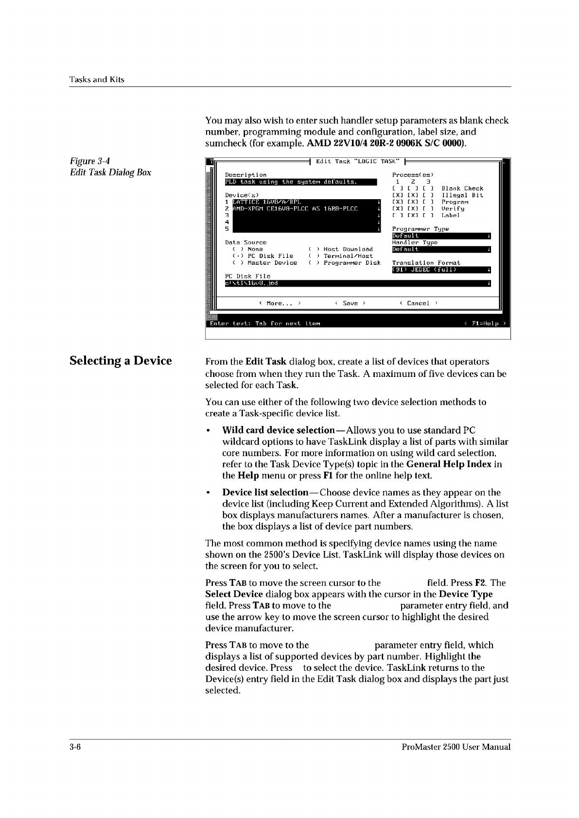
Figure
3-4
Edit
Task
Dialog
Box
You
may
also
wish
to
enter
such
handler
setup
parameters
as
blank
check
number,
programming
module
and
configuration,
label
size,
and
sumcheck
(for
example,
AMD
22V10/4
20R-2
0906K
S/C
0000).
Selecting
a
Device
From
the
Edit
Task
dialog
box,
create
a
list
of
devices
that
operators
choose
from
when
they
run
the
Task.
A
maximum
of
five
devices
can
be
selected
for
each
Task.
You
can
use
either
of
the
following
two
device
selection
methods
to
create
a
Task-specific
device
list.
•
Wild
card
device
selection
—
Allows
you
to
use
standard
PC
wildcard
options
to
have
TaskLink
display
a
list
of
parts
with
similar
core
numbers.
For
more
information
on
using
wild
card
selection,
refer
to
the
Task
Device
Type(s)
topic
in
the
General
Help
Index
in
the
Help
menu
or
press
Fl
for
the
online
help
text.
•
Device
list
selection
—
Choose
device
names
as
they
appear
on
the
device
list
(including
Keep
Current
and
Extended
Algorithms).
A
list
box
displays
manufacturers
names.
After
a
manufacturer
is
chosen,
the
box
displays
a
list
of
device
part
numbers.
The
most
common
method
is
specifying
device
names
using
the
name
shown
on
the
2500's
Device
List.
TaskLink
will
display
those
devices
on
the
screen
for
you
to
select.
Press
Tab
to
move
the
screen
cursor
to
the
field.
Press
F2.
The
Select
Device
dialog
box
appears
with
the
cursor
in
the
Device
Type
field.
Press
Tab
to
move
to
the
parameter
entry
field,
and
use
the
arrow
key
to
move
the
screen
cursor
to
highlight
the
desired
device
manufacturer.
Press
Tab
to
move
to
the
parameter
entry
field,
which
displays
a
list
of
supported
devices
by
part
number.
Highlight
the
desired
device.
Press
to
select
the
device.
TaskLink
returns
to
the
Device
(s)
entry
field
in
the
Edit
Task
dialog
box
and
displays
the
part
just
selected.
1
z
3
4
5
3-6
ProMaster
2500
User
Manual