2500_Users_Manual-.pdf - 第86页
↵ Tasks and Kits Figure 3-15 Serialization Parameters Dialog Box Serialization Method — select File when operating with an ESP. (The Memory Buffer selection is offered to maintain compatibility with a previous product an…
Tasks
and
Kits
Serializing
Devices
You
may
want
to
program
a
serial
number
into
the
devices
and/or
print
the
number
on
the
label.
TaskLink's
Serialization...
option
offers
an
opportunity
to
do
this
in
software.
A
sample
serialization
program
called
serializ.exe
is
provided
with
TaskLink.
For
detailed
information
on
the
serialization
program,
refer
to
the
External
Serialization
Program
section
on
page
3-25
and
to
the
online
help
topic
“Writing
a
Serialization
Program”
under
TaskLink's
General
Help
Index.
To
implement
serialization
features
not
provided
by
serializ.exe,
you
will
need
to
write
a
short
external
serialization
program
(ESP)
to
generate
your
serial
number
and
save
it
in
an
ASCII
file
for
TaskLink
to
use.
To
print
a
serial
number
on
a
label,
enter
a
percent
sign
(%)
in
the
label
text
field
(ProMaster
2500
dialog
box)
for
each
character
to
be
printed
on
the
label
(refer
to
the
command
line
length
parameter
Note:
You
must
have
UI
5
version
1.06
or
greater
to
print
a
serial
number.
Figure
3-16
shows
the
process
steps
in
creating
a
file
to
be
used
for
serializing
devices.
The
Program
line
in
TaskLink's
Serialization
Parameters
screen
(see
Figure
3-15)
allows
you
to
enter
the
executable
name
for
your
external
program
(ESP).
You
can
also
include
the
path
and
command
line
arguments
that
define
the
characteristics
of
the
serial
number
to
pass
to
the
ESP.
The
ESP
is
called
from
the
command
line
using
a
command
similar
to
the
following:
drive:
\
path
\file_name
where
drive
is
the
drive
where
the
ESP
resides,
path
is
a
valid
DOS
path
to
the
subdirectory
where
the
ESP
is
written,
and
flle_name
is
the
ESP
executable
file
name
and
extension.
3-22
ProMaster
2500
User
Manual
↵
Tasks
and
Kits
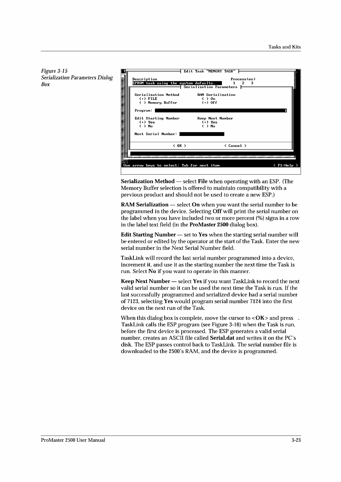
Figure
3-15
Serialization
Parameters
Dialog
Box
Serialization
Method
—
select
File
when
operating
with
an
ESP.
(The
Memory
Buffer
selection
is
offered
to
maintain
compatibility
with
a
previous
product
and
should
not
be
used
to
create
a
new
ESP.)
RAM
Serialization
—
select
On
when
you
want
the
serial
number
to
be
programmed
in
the
device.
Selecting
Off
will
print
the
serial
number
on
the
label
when
you
have
included
two
or
more
percent
(%)
signs
in
a
row
in
the
label
text
field
(in
the
ProMaster
2500
dialog
box).
Edit
Starting
Number
—
set
to
Yes
when
the
starting
serial
number
will
be
entered
or
edited
by
the
operator
at
the
start
of
the
Task.
Enter
the
new
serial
number
in
the
Next
Serial
Number
field.
TaskLink
will
record
the
last
serial
number
programmed
into
a
device,
increment
it,
and
use
it
as
the
starting
number
the
next
time
the
Task
is
run.
Select
No
if
you
want
to
operate
in
this
manner.
Keep
Next
Number
—
select
Yes
if
you
want
TaskLink
to
record
the
next
valid
serial
number
so
it
can
be
used
the
next
time
the
Task
is
run.
If
the
last
successfully
programmed
and
serialized
device
had
a
serial
number
of
7123,
selecting
Yes
would
program
serial
number
7124
into
the
first
device
on
the
next
run
of
the
Task.
When
this
dialog
box
is
complete,
move
the
cursor
to
<
OK>
and
press
.
TaskLink
calls
the
ESP
program
(see
Figure
3-16)
when
the
Task
is
run,
before
the
first
device
is
processed.
The
ESP
generates
a
valid
serial
number,
creates
an
ASCII
file
called
SeriaLdat
and
writes
it
on
the
PC
s
disk.
The
ESP
passes
control
back
to
TaskLink.
The
serial
number
file
is
downloaded
to
the
2500's
RAM,
and
the
device
is
programmed.
ProMaster
2500
User
Manual
3-23
Placement
↵
↵
Tasks
and
Kits
Saving
the
Task
Other
Logic
Parameters
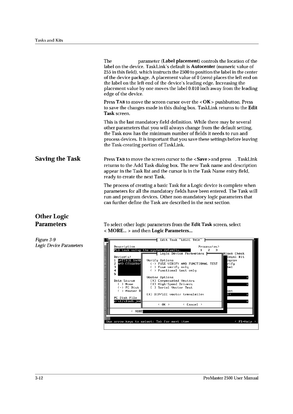
Figure
3-9
Logic
Device
Parameters
The
parameter
(Label
placement)
controls
the
location
of
the
label
on
the
device.
TaskLink's
default
is
Autocenter
(numeric
value
of
255
in
this
field),
which
instructs
the
2500
to
position
the
label
in
the
center
of
the
device
package.
A
placement
value
of
0
(zero)
places
the
left
end
on
the
label
on
the
left
end
of
the
device's
leading
edge.
Increasing
the
placement
value
by
one
moves
the
label
0.010
inch
away
from
the
leading
edge
of
the
device.
Press
Tab
to
move
the
screen
cursor
over
the
<
OK>
pushbutton.
Press
to
save
the
changes
made
in
this
dialog
box.
TaskLink
returns
to
the
Edit
Task
screen.
This
is
the
last
mandatory
field
definition.
While
there
may
be
several
other
parameters
that
you
will
always
change
from
the
default
setting,
the
Task
now
has
the
minimum
number
of
fields
it
needs
to
run
and
process
devices.
It
is
important
that
you
save
these
settings
before
leaving
the
Task-creating
portion
of
TaskLink.
Press
Tab
to
move
the
screen
cursor
to
the
<
Save
>
and
press
.
TaskLink
returns
to
the
Add
Task
dialog
box.
The
new
Task
name
and
description
appear
in
the
Task
list
and
the
cursor
is
in
the
Task
Name
entry
field,
ready
to
create
the
next
Task.
The
process
of
creating
a
basic
Task
for
a
Logic
device
is
complete
when
parameters
for
all
the
mandatory
fields
have
been
entered.
The
Task
will
run
and
program
devices.
Other
non-mandatory
logic
parameters
that
can
further
define
the
Task
are
described
in
the
next
section.
To
select
other
logic
parameters
from
the
Edit
Task
screen,
select
<
MORE...
>
and
then
Logic
Parameters...
Edit
Task
"LOGIC
TASK"
Descript
i
on
|
Logic
Device
Parameters
p
DeuiceC
s)
[
X]
DIP/LCC
vector
translation
PC
Disk
File
<
Cancel
>
<
OK
>
<
MORE
PLD
task
using
the
system
defaults.
II
c
:
\tl\16v8.
Jedi
II
Fl=Help
>
LATTICE
16U8
AMD
CE16U8H/
1
Z
Blank
Check
Ilegal
Bit
ogran
rify
bel
arrow
keys
to
select:
Tab
for
next
it
巳
e
Data
Source
( )
None
(
)
PC
Disk
(
)
Master
D
Uerif
y
Options
(
•
)
FUSE
UERIFY
AND
FUNCTIONAL
TEST
( )
Fuse
verify
only
(
)
Functional
test
only
Uector
Options
[
X]
CoMpensated
Uectors
[XI
High-Speed
Drivers
E
]
Serial
Uector
Test
Process(
es)
1
Z
3
3-12
ProMaster
2500
User
Manual