2500_Users_Manual-.pdf - 第88页
Tasks and Kits TaskLink displays the Logic Device Parameters dialog box with these main options: • Verify Options — Select one option from the three offered. • Fuse verify only — Compares the fuses programmed in the logi…
Placement
↵
↵
Tasks
and
Kits
Saving
the
Task
Other
Logic
Parameters
Figure
3-9
Logic
Device
Parameters
The
parameter
(Label
placement)
controls
the
location
of
the
label
on
the
device.
TaskLink's
default
is
Autocenter
(numeric
value
of
255
in
this
field),
which
instructs
the
2500
to
position
the
label
in
the
center
of
the
device
package.
A
placement
value
of
0
(zero)
places
the
left
end
on
the
label
on
the
left
end
of
the
device's
leading
edge.
Increasing
the
placement
value
by
one
moves
the
label
0.010
inch
away
from
the
leading
edge
of
the
device.
Press
Tab
to
move
the
screen
cursor
over
the
<
OK>
pushbutton.
Press
to
save
the
changes
made
in
this
dialog
box.
TaskLink
returns
to
the
Edit
Task
screen.
This
is
the
last
mandatory
field
definition.
While
there
may
be
several
other
parameters
that
you
will
always
change
from
the
default
setting,
the
Task
now
has
the
minimum
number
of
fields
it
needs
to
run
and
process
devices.
It
is
important
that
you
save
these
settings
before
leaving
the
Task-creating
portion
of
TaskLink.
Press
Tab
to
move
the
screen
cursor
to
the
<
Save
>
and
press
.
TaskLink
returns
to
the
Add
Task
dialog
box.
The
new
Task
name
and
description
appear
in
the
Task
list
and
the
cursor
is
in
the
Task
Name
entry
field,
ready
to
create
the
next
Task.
The
process
of
creating
a
basic
Task
for
a
Logic
device
is
complete
when
parameters
for
all
the
mandatory
fields
have
been
entered.
The
Task
will
run
and
program
devices.
Other
non-mandatory
logic
parameters
that
can
further
define
the
Task
are
described
in
the
next
section.
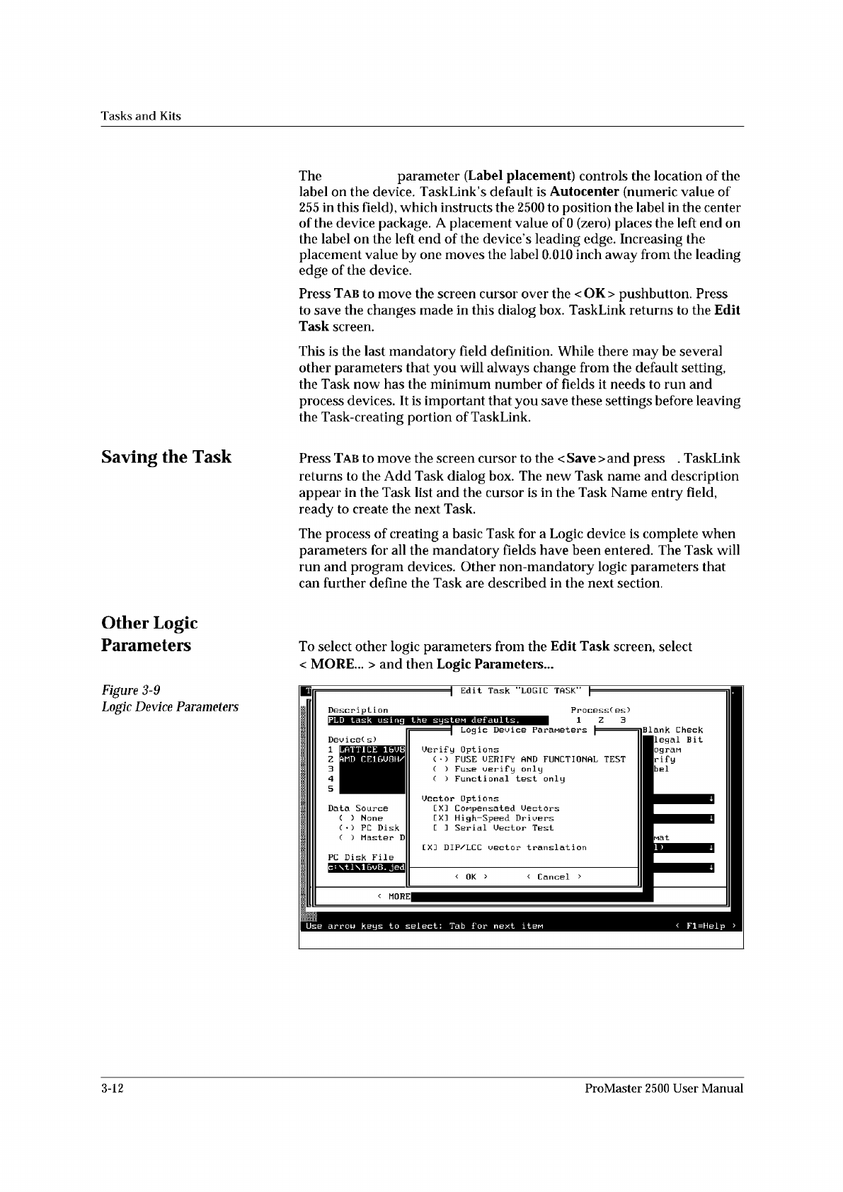
To
select
other
logic
parameters
from
the
Edit
Task
screen,
select
<
MORE...
>
and
then
Logic
Parameters...
Edit
Task
"LOGIC
TASK"
Descript
i
on
|
Logic
Device
Parameters
p
DeuiceC
s)
[
X]
DIP/LCC
vector
translation
PC
Disk
File
<
Cancel
>
<
OK
>
<
MORE
PLD
task
using
the
system
defaults.
II
c
:
\tl\16v8.
Jedi
II
Fl=Help
>
LATTICE
16U8
AMD
CE16U8H/
1
Z
Blank
Check
Ilegal
Bit
ogran
rify
bel
arrow
keys
to
select:
Tab
for
next
it
巳
e
Data
Source
( )
None
(
)
PC
Disk
(
)
Master
D
Uerif
y
Options
(
•
)
FUSE
UERIFY
AND
FUNCTIONAL
TEST
( )
Fuse
verify
only
(
)
Functional
test
only
Uector
Options
[
X]
CoMpensated
Uectors
[XI
High-Speed
Drivers
E
]
Serial
Uector
Test
Process(
es)
1
Z
3
3-12
ProMaster
2500
User
Manual
Tasks
and
Kits
TaskLink
displays
the
Logic
Device
Parameters
dialog
box
with
these
main
options:
•
Verify
Options
—
Select
one
option
from
the
three
offered.
•
Fuse
verify
only
—
Compares
the
fuses
programmed
in
the
logic
device
with
the
pattern
in
the
2500's
RAM.
No
structured
test
vectors
are
applied
to
the
device
even
if
they
were
downloaded
in
the
JEDEC
data
file.
•
Functional
test
only
—
Verifies
the
programmed
device
using
the
structured
test
vectors
downloaded
with
the
JEDEC
data
file.
The
fuses
in
the
device
are
not
checked.
This
is
useful
when
the
devices
have
had
their
security
fuse
programmed
so
that
the
fuse
pattern
in
their
main
array
can
no
longer
be
read
by
the
programmer.
Vectors
written
for
the
device
will
confirm
that
the
device
is
functioning
correctly
if
all
vectors
pass.
•
Fuse
verify
and
functional
test
(default)
—
Verifies
the
programmed
device
by
comparing
the
device
fuses
against
the
fuses
in
RAM.
If
the
device
passes,
the
test
vectors
are
applied
to
the
device.
If
all
the
fuses
verify
and
the
vectors
pass,
the
device
is
labeled
and
placed
in
the
pass
output
tube.
•
Vector
Options
—
Select
any
combination
of
these
three
options
to
change
the
way
logic
test
vectors
are
applied
to
your
device
during
the
verify
cycle.
These
test
vector
options
may
improve
the
yield
of
devices
that
pass
fuse
verify
but
fail
test
vectors.
Certain
PLD
Tasks
may
experience
a
higher
failure
rate
when
test
vectors
are
run.
These
failures
are
usually
a
combination
of
conditions
in
the
design
(as
defined
in
the
JEDEC
file),
the
internal
characteristics
of
the
device,
and
the
way
the
2500
applies
vectors.
These
test
vector
options
affect
the
way
the
2500
applies
the
file's
test
vectors
to
the
device
in
an
attempt
to
improve
the
number
of
devices
that
pass
test
vectors.
•
Compensated
Vectors
—
Some
PLD
designs
create
combinatorial
latches
on
registered
outputs
and
may
fail
test
vectors
even
though
the
devices
have
been
programmed
correctly.
This
is
most
often
due
to
a
combination
of
factors
including
the
specific
PLD
design,
the
device's
internal
hardware
characteristics,
and
the
programming
electronics
in
the
2500.
If
this
parameter
has
been
disabled
and
a
large
number
of
combinatorial
output
devices
are
failing
test
vectors,
selecting
Compensated
Vectors
may
improve
the
yield.
This
parameter
is
enabled
by
default
in
TaskLink.
•
High-speed
Drivers
—
Some
PLD
designs,
when
implemented
in
certain
high-speed
PLDs,
will
fail
test
vectors
even
though
the
device
programmed
correctly
and
functions
correctly
in-circuit.
The
High-speed
Drivers
option
(which
is
enabled
by
default)
applies
the
vector
inputs
to
the
device
at
a
higher
speed,
using
a
higher
current
drive.
Note:
Because
this
option
Is
enabled
by
default,
be
careful
how
you
write
your
drivers.
If
the
JEDEC
file
test
vectors
have
not
been
written
correctly,
this
higher
current
applied
to
a
bi-directional
input
pin
might
damage
some
devices.
ProMaster
2500
User
Manual
3-13
Device(s)
Data Source
Data File Translation Format
Process(es)
< More... > Handling/Labeling Parameters...
Tasks
and
Kits
Dev
ice(
s)
k
Z751ZX
PC
Disk
File
|u47b.
£93
Data
Source
( )
None
(
)
Host
Download
(♦)
PC
Disk
File
( )
Terninal/Host
( )
Master
Device
(
)
PrograMMer
Disk
Description
lEPROM
task
using
the
systen
defaults.
Process(
es)
12m
[][][]
Blank
Check
[XJ
[
J
[
J
rx]
r
]
r
i
[>□
rx]
[
i
rx:
rxi
[
i
Illegal
B
it
PrograM
Uerify
Label
PrograMMer
Type
Default
Handler
Type
Default,
Translation
Format
(83)
Intel
MCS-86
Edit
Task
"MEMORY
TASK"
Enter
text
;
Tab
for
next
iteM
<
Fl=Help
Data
Sumcheck
•
Serial
Vector
Test
—
The
2500
applies
test
vectors
to
the
device
inputs
in
parallel.
If
the
PLD
design
requires
certain
input
pins
to
be
applied
before
others,
the
JEDEC
standard
states
that
the
test
vectors
must
be
written
to
enforce
that
particular
order.
When
this
option
has
been
selected,
the
2500
applies
the
vector
inputs
starting
with
device
pin
1
and
continuing
in
numeric
order
to
the
last
input.
This
option
will
not
harm
the
device
and
should
be
used
as
a
troubleshooting
tool
when
a
large
number
of
devices
are
passing
fuse
verify
but
failing
test
vectors.
It
is
not
enabled
by
default.
•
DIP/LCC
vector
translation
—
In
some
instances
the
test
vectors
in
the
JEDEC
file
were
written
for
a
DIP
device
but
will
be
used
to
verify
a
PLCC
part.
When
this
translation
option
is
selected,
the
2500
automatically
translates
the
DIP
test
vectors
during
the
download
into
the
correct
format
to
test
the
PLCC/LCC
part.
This
optional
parameter,
when
selected,
will
check
the
sumcheck
at
the
end
of
the
file
transfer
with
the
sumcheck
entered
in
this
Task
field.
For
additional
information
on
this
parameter,
see
page
3-18.
Creating
a
Task
for
a
Memory
Device
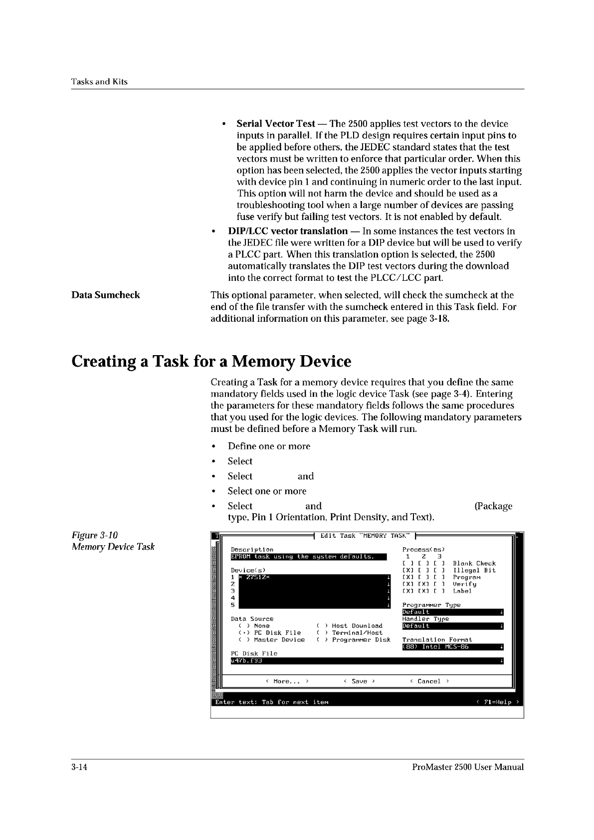
Creating
a
Task
for
a
memory
device
requires
that
you
define
the
same
mandatory
fields
used
in
the
logic
device
Task
(see
page
3-4).
Entering
the
parameters
for
these
mandatory
fields
follows
the
same
procedures
that
you
used
for
the
logic
devices.
The
following
mandatory
parameters
must
be
defined
before
a
Memory
Task
will
run.
•
Define
one
or
more
•
Select
•
Select
and
•
Select
one
or
more
•
Select
and
(Package
type,
Pin
1
Orientation,
Print
Density,
and
Text).
Figure
3-10
Memory
Device
Task
1
z
3
4
5
3-14
ProMaster
2500
User
Manual