2500_Users_Manual-.pdf - 第96页
Tasks and Kits Figure 3-14 General Parameters Dialog Box Remote Control commands in Appendix E. For example, you might use these commands if you want to program a device but disable the verify option. The Edit Task dialo…
↵
↵
Tasks
and
Kits
Introduction
to
Kits
Kits
are
Tasks
that
have
been
daisy-chained
together
so
several
can
be
run
as
one
large
job.
The
most
common
use
for
Kits
is
to
string
together
the
separate
Tasks
used
to
program
all
the
devices
for
a
single
board.
In
Figure
3-23
there
are
four
devices
that
must
be
programmed
and
labeled
for
the
sample
board.
Each
device
has
one
Task
that
controls
the
process
for
producing
that
device.
The
Kit
acts
like
a
super-Task.
To
illustrate
this
point,
assume
that
60
boards
need
to
be
built.
When
the
Kit
fbr
this
board
is
run,
the
Task
1
pass
limit
is
set
to
60
devices.
When
that
count
is
reached,
TaskLink
displays
a
message
prompting
the
system
operator
to
change
over
for
the
second
Task.
When
ready
for
Task
2,
the
operator
presses
.
TaskLink
starts
Task
2,
and
60
devices
for
that
Task
are
programmed.
This
process
continues
for
Task
3
and
Task
4.
The
messages
screens
are
typically
used
when
the
Tasks
define
devices
using
different
package
types
(Task
1
uses
DIPs
and
Task
2
uses
PLCCs).
In
this
case,
a
message
screen
might
remind
the
operator
about
the
steps
required
to
change
over
from
one
package
type
to
another.
A
Kit
can
include
a
maximum
of
20
Tasks.
All
the
Tasks
for
a
Kit
must
be
in
the
same
database
file
(called
the
Source
Database
in
the
Kit
dialog
box),
but
the
Kit
can
be
stored
in
the
Source
Database
or
a
different
database
file.
When
the
Kit
is
run,
the
system
operator
specifies
the
number
of
Kits
(equal
to
the
number
of
complete
boards)
to
be
built.
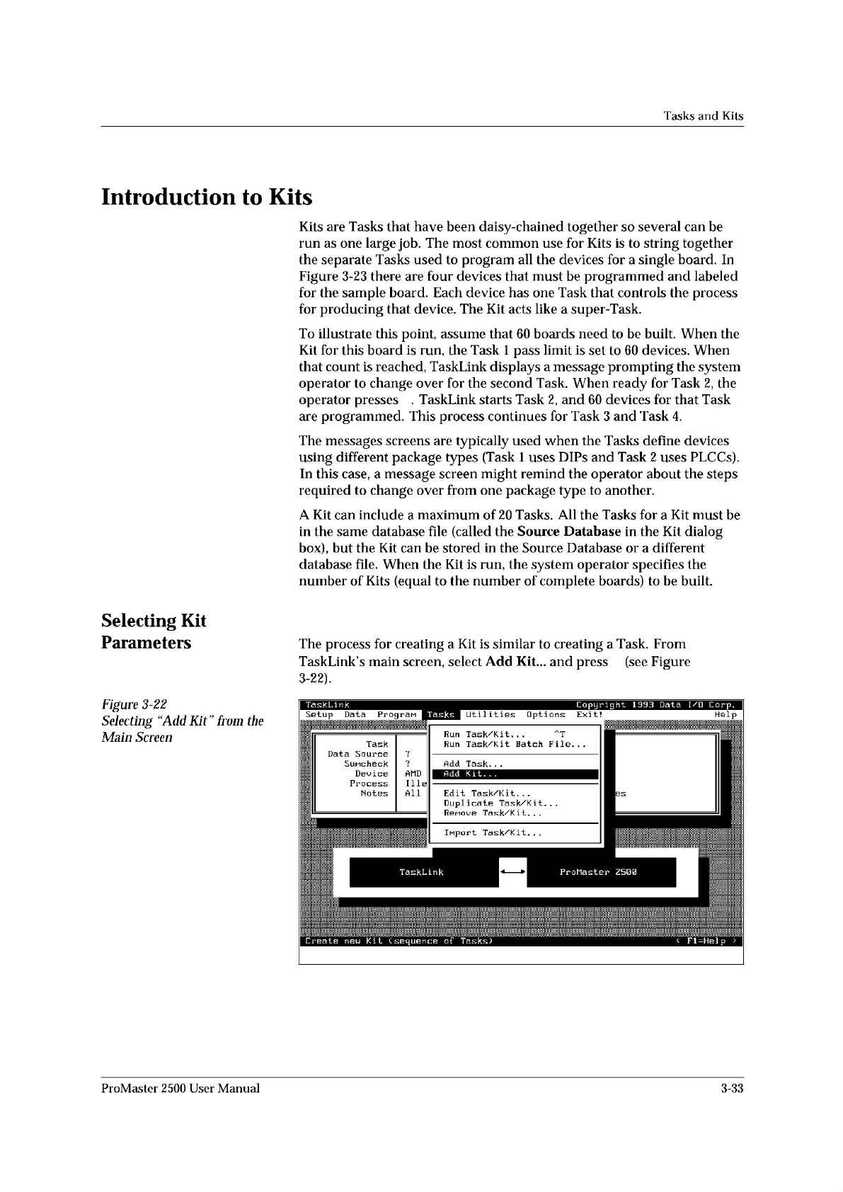
Selecting
Kit
Parameters
The
process
for
creating
a
Kit
is
similar
to
creating
a
Task.
From
TaskLink
s
main
screen,
select
Add
Kit...
and
press
(see
Figure
3-22).
Figure
3-22
Selecting
“Add
Kit”
from
t
加
Main
Screen
ProMaster
2500
User
Manual
3-33
Tasks
and
Kits
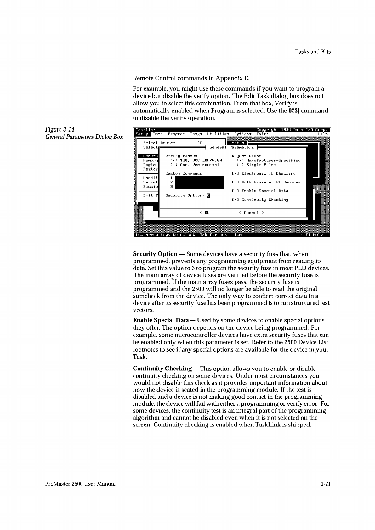
Figure
3-14
General
Parameters
Dialog
Box
Remote
Control
commands
in
Appendix
E.
For
example,
you
might
use
these
commands
if
you
want
to
program
a
device
but
disable
the
verify
option.
The
Edit
Task
dialog
box
does
not
allow
you
to
select
this
combination.
From
that
box,
Verify
is
automatically
enabled
when
Program
is
selected.
Use
the
023]
command
to
disable
the
verify
operation.
Security
Option
—
Some
devices
have
a
security
fuse
that,
when
programmed,
prevents
any
programming
equipment
from
reading
its
data.
Set
this
value
to
3
to
program
the
security
fuse
in
most
PLD
devices.
The
main
array
of
device
fuses
are
verified
before
the
security
fuse
is
programmed.
If
the
main
array
fuses
pass,
the
security
fuse
is
programmed
and
the
2500
will
no
longer
be
able
to
read
the
original
sumcheck
from
the
device.
The
only
way
to
confirm
correct
data
in
a
device
after
its
security
fuse
has
been
programmed
is
to
run
structured
test
vectors.
Enable
Special
Data
—
Used
by
some
devices
to
enable
special
options
they
offer.
The
option
depends
on
the
device
being
programmed.
For
example,
some
microcontroller
devices
have
extra
security
fuses
that
can
be
enabled
only
when
this
parameter
is
set.
Refer
to
the
2500
Device
List
footnotes
to
see
if
any
special
options
are
available
for
the
device
in
your
Task.
Continuity
Checking
—
This
option
allows
you
to
enable
or
disable
continuity
checking
on
some
devices.
Under
most
circumstances
you
would
not
disable
this
check
as
it
provides
important
information
about
how
the
device
is
seated
in
the
programming
module.
If
the
test
is
disabled
and
a
device
is
not
making
good
contact
in
the
programming
module,
the
device
will
fail
with
either
a
programming
or
verify
error.
For
some
devices,
the
continuity
test
is
an
integral
part
of
the
programming
algorithm
and
cannot
be
disabled
even
when
it
is
not
selected
on
the
screen.
Continuity
checking
is
enabled
when
TaskLink
is
shipped.
ProMaster
2500
User
Manual
3-21
Tasks
and
Kits
Serializing
Devices
You
may
want
to
program
a
serial
number
into
the
devices
and/or
print
the
number
on
the
label.
TaskLink's
Serialization...
option
offers
an
opportunity
to
do
this
in
software.
A
sample
serialization
program
called
serializ.exe
is
provided
with
TaskLink.
For
detailed
information
on
the
serialization
program,
refer
to
the
External
Serialization
Program
section
on
page
3-25
and
to
the
online
help
topic
“Writing
a
Serialization
Program”
under
TaskLink's
General
Help
Index.
To
implement
serialization
features
not
provided
by
serializ.exe,
you
will
need
to
write
a
short
external
serialization
program
(ESP)
to
generate
your
serial
number
and
save
it
in
an
ASCII
file
for
TaskLink
to
use.
To
print
a
serial
number
on
a
label,
enter
a
percent
sign
(%)
in
the
label
text
field
(ProMaster
2500
dialog
box)
for
each
character
to
be
printed
on
the
label
(refer
to
the
command
line
length
parameter
Note:
You
must
have
UI
5
version
1.06
or
greater
to
print
a
serial
number.
Figure
3-16
shows
the
process
steps
in
creating
a
file
to
be
used
for
serializing
devices.
The
Program
line
in
TaskLink's
Serialization
Parameters
screen
(see
Figure
3-15)
allows
you
to
enter
the
executable
name
for
your
external
program
(ESP).
You
can
also
include
the
path
and
command
line
arguments
that
define
the
characteristics
of
the
serial
number
to
pass
to
the
ESP.
The
ESP
is
called
from
the
command
line
using
a
command
similar
to
the
following:
drive:
\
path
\file_name
where
drive
is
the
drive
where
the
ESP
resides,
path
is
a
valid
DOS
path
to
the
subdirectory
where
the
ESP
is
written,
and
flle_name
is
the
ESP
executable
file
name
and
extension.
3-22
ProMaster
2500
User
Manual