00196478-08_MM_SX12DX12_en.pdf - 第50页
Major Maintenance Maintenance Tasks for Base Machine 5.2.3 Final Work 50 Maintenance Manual SIPLACE SX1/SX2/DX1/DX2 5.2.2.6 5 . 2 . 2 . 6 C h e c k in g t h e G u id e R o lle r s o n t h e P r o t e c t iv e C o v e r s…
Major Maintenance
5.2.2 Performing Maintenance Tasks Maintenance Tasks for Base Machine
Maintenance Manual SIPLACE SX1/SX2/DX1/DX2 49
5.2.2.5
5.2.2.5 Checking/Cleaning/Replacing the Gas Pressure Shock Absorbers on the Protective Covers
Checking/Cleaning/Replacing the Gas Pressure Shock Absorbers on the Protective Covers
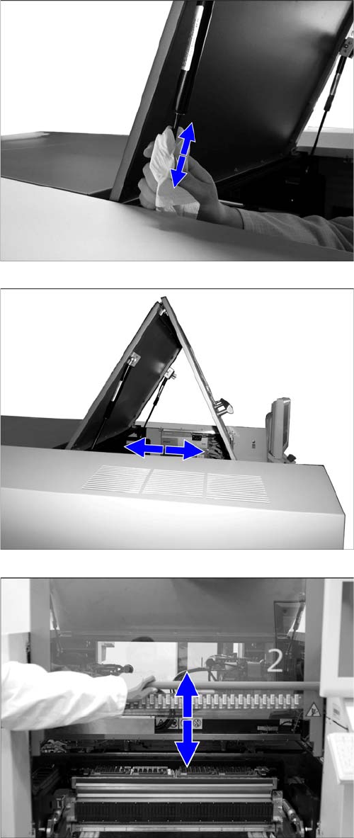
► Open the protective covers.
► Wipe the sliding surfaces of the gas pressure shock
absorbers clean with a lint-free cloth.
► Open and close the cover several times in succes-
sion.
► No oil should be visible on the piston. Otherwise, the
gas pressure shock absorbers must be replaced by
authorized personnel. For removal and installation
details, read the service manual for your machine.
► Open the protective cover.
► Pull the protective cover approx. 30 cm horizontally
towards you and then release it again.
If the cover does not open completely again, the gas
pressure shock absorbers must be replaced by au-
thorized personnel.
For removal and installation details, refer to the ser-
vice manual for your machine.
► Pull the protective cover vertically to a position be-
tween the top and bottom positions and then release
it again.
The cover must either stay in position without help or
open a bit further. If it closes on its own, the gas pres-
sure shock absorbers must be replaced by author-
ized personnel.
For removal and installation details, read the service
manual for your machine.
► Close the protective cover.
► Repeat these steps for all protective covers.
Major Maintenance
Maintenance Tasks for Base Machine 5.2.3 Final Work
50 Maintenance Manual SIPLACE SX1/SX2/DX1/DX2
5.2.2.6
5.2.2.6 Checking the Guide Rollers on the Protective Covers
Checking the Guide Rollers on the Protective Covers
5.2.2.7
5.2.2.7 Checking the Buffers on the Protective Covers
Checking the Buffers on the Protective Covers
5.2.3
5.2.3 Final Work
Final Work
► Reestablish the compressed air supply to the machine.
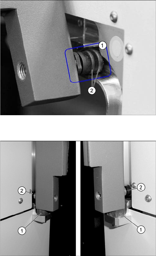
► Check the guide roller (1) for damage. If the guide
roller is damaged, it must be replaced by authorized
personnel. For adjusting the flap cover and for other
information, read the Service manual.
► Check the O-rings (2) on the guide roller. If the O-
rings are damaged or missing, they must be replaced
by authorized personnel. For removal and installation
details, read the Service manual.
► Repeat these steps for all guide rollers (two per cov-
er).
► Pull the protective cover completely downwards.
► Check if the roller (2) touches the lower buffer (1) in
the guidance.
► If the roller touches the buffer, the buffer has to be re-
placed by authorized personnel. For adjusting the
flap cover and for other information, read the Service
manual.
► Repeat these steps for all buffers (two buffers per
protective cover).
Major Maintenance
5.3.1 Tools, Consumables, Spare and Wear Parts Maintenance Tasks for the Component Feed Device
Maintenance Manual SIPLACE SX1/SX2/DX1/DX2 51
5.3
5.3 Maintenance Tasks for the Component Feed Device
Maintenance Tasks for the Component Feed Device
5.3.1
5.3.1 Tools, Consumables, Spare and Wear Parts
Tools, Consumables, Spare and Wear Parts
▪ SIPLACE cleaning tissue [00315253-xx]
▪ Protective latex gloves [00372972-xx]
▪ Oil spray Surface Shield 400 ml [00328575-xx]
▪ Interflon Fin Grease [03020782-xx]
▪ Lint-free cloths [03082092-xx]
▪ Klüberplex BEM 34-132 lubricant, 1 kg tin [00374565-xx]
▪ Sheet of DIN A3 paper (or 2x A4)
▪ Adhesive tape strips
▪ Scissors
▪ ESD wristband [00320279-xx]
▪ Lubrication nipple DIN71412-A-M6 – straight (tape cutter) [03036936-xx], if required
▪ Grease gun with hose for Y axis (volume applied: approx. 0.4 g) [00374563-xx]
▪ Ethanol
Isopropanol – IPA can be used as an alternative.
5.3.2
5.3.2 Performing Maintenance Tasks
Performing Maintenance Tasks
5.3.2.1
5.3.2.1 Function Test of Used Tape Cutter
Function Test of Used Tape Cutter
Risk of injury when working near the tap e cutter
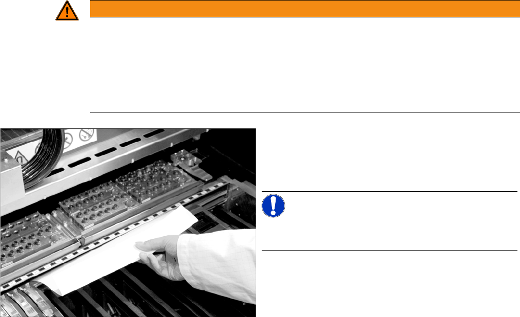
► Take the sheet of paper out of the empty tape duct again.
If it has not been cut through accurately, the cutting blades must be cleaned or replaced. This task
must be carried out by authorized personnel. For removal and installation details, read the Service
manual.
WARNING
Risk of injury when working near the cutter.
When working in the area of the tape cutter, move the component trolley out of the machine
and disconnect the machine from the mains supply and the compressed air supply.
► Wait until the operating pressure has dropped to 0 MPa.
► Always secure the machine against unauthorized reactivation.
► Do not reach into the tape cutter.
➢ The machine and the changeover tables within the
machine must be switched on for the next test.
► Insert a sheet of DIN A3 paper or two DIN A4 sheets
attached to one another into the empty tape duct.
NOTICE!
A DIN A4 sheet on its own is too short to reach the tape
cutter.
► Attach the sheet of paper with adhesive tape to the
empty tape duct.
Make sure that there is no paper protruding upwards
in the placement head travel range.
► Start the cutting process in the software.