NR_Mechanischer_Stopper.pdf - 第129页
Assembly Instructions PCB Stopper Single Conveyor SIPLACE S-27HM / HS-60 / D4 / D 3 / HF- / X-Series Edition 06/2007 129 12 Assembly Instructions PCB S topper SIPLACE S-27HM / HS-60 / D4 / D3 / HF- / X-Series AT T E N T …
Assembly Instructions PCB Stopper Single Conveyor SIPLACE S-27HM / HS-60 / D4 / D3 / HF- / X-Series
Edition 06/2007
128
Assembly Instructions PCB Stopper Single Conveyor SIPLACE S-27HM / HS-60 / D4 / D3 / HF- / X-Series
Edition 06/2007
129
12 Assembly Instructions PCB Stopper
SIPLACE S-27HM / HS-60 / D4 / D3 /
HF- / X-Series
ATTENTION: This internal document describes service work to SIPLACE placement machines,
which may only be performed by specially trained Siemens service technicians. 12
12
The description of the installation process is based on the example of a dual conveyor.Single con-
veyor installation is carried out similarly. Attention is drawn to significant differences.
12
12.1 Functional description
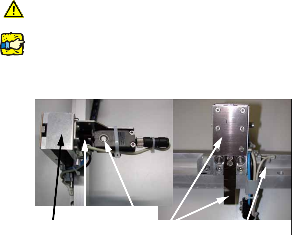
Fig. 106
The optional mechanical stopper was developed for placement machines of the X-Series, HF-Se-
ries, HS-60, D3, D4 and S-27 HM. These are fitted as standard with modular PCB conveyors and
laser light barriers for stopping the printed circuit boards.
Placement machines of the types HS-50, F5 HM and S-25 HM on the other hand have a PCB con-
veyor with mechanical stopper. 12
Stopper, basic unit
Rotating cylinder
Sonar sensor
Stopper
Stopper sensor top/bottom
Assembly Instructions PCB Stopper Single Conveyor SIPLACE S-27HM / HS-60 / D4 / D3 / HF- / X-Series
Edition 06/2007
130
You should install the optional mechanical stopper on placement machines with modular PCB
conveyor if you wish to operate machines in a mixed line. This will enable you to define a uniform
stopper position for the printed circuit boards of both PCB conveyor variants. 12
As soon as a PCB is ready for the placement area, the stopper is driven out. The PCB moves into
the placement area. The sonar sensor detects the PCB and reduces the conveyor speed so that
the PCB comes up against the stopper "at reduced speed". The PCB is clamped upward and the
stop rail of the PCB stopper is drawn in. From this point onward, production continues as usual
with the standard process. 12
12.2 Restrictions
– Station computer software:
– D- and X-series: at least 601.03
– S27, HS-60, HF-series: at least 505.03
– The stop rail of the stopper is 7 mm wide above the PCB; for stability reasons the stopper is
15 mm wide below the PCB. This means that components on the underside of the PCB that
protrude forward beyond the PCB in the direction of transport must be at a minimum distance
of 16 mm from each other.
– Minimum PCB width 52 mm
– The maximum impact of the PCB against the stopper is the same as the impact for the HS-50.
The brake ramp is introduced over the sonar sensor in the same way as for the HS-50 con-
veyor.
– The tolerance of the stop position (repeat accuracy) is +/- 0.5 mm, the same as for the laser
light barrier.
– The tolerance of the stopper/laser light barrier is +/- 1 mm.
Should there be any problems with fiducial detection, it will be necessary to measure the PCB
reference corner again in SITEST.
– The mechanical stopper does not work in conjunction with the PCB alignment, the SOKOS ce-
ramic substrate centering or vacuum tooling.
– The stopper for long boards can be operated in conjunction with the mechanical stopper.
– The stopper must be activated in the SITEST. After this the machine needs to be restarted.
– Simple switching between the stopper and the laser light barrier is only possible via the SIT-
EST. The placement machine must be restarted for this.
– It is not possible to remove the stopper mechanically for a short period.
– For service tools or fine calibration, the stopper needs to be detached and removed from the
guide rail. The laser light barrier needs to be activated in the SITEST.