NR_Mechanischer_Stopper.pdf - 第131页
Assembly Instructions PCB Stopper Single Conveyor SIPLACE S-27HM / HS-60 / D4 / D 3 / HF- / X-Series Edition 06/2007 131 – The option can be retrofitted on any conveyor su pplied to date. – Conversion times (witho ut sof…
Assembly Instructions PCB Stopper Single Conveyor SIPLACE S-27HM / HS-60 / D4 / D3 / HF- / X-Series
Edition 06/2007
130
You should install the optional mechanical stopper on placement machines with modular PCB
conveyor if you wish to operate machines in a mixed line. This will enable you to define a uniform
stopper position for the printed circuit boards of both PCB conveyor variants. 12
As soon as a PCB is ready for the placement area, the stopper is driven out. The PCB moves into
the placement area. The sonar sensor detects the PCB and reduces the conveyor speed so that
the PCB comes up against the stopper "at reduced speed". The PCB is clamped upward and the
stop rail of the PCB stopper is drawn in. From this point onward, production continues as usual
with the standard process. 12
12.2 Restrictions
– Station computer software:
– D- and X-series: at least 601.03
– S27, HS-60, HF-series: at least 505.03
– The stop rail of the stopper is 7 mm wide above the PCB; for stability reasons the stopper is
15 mm wide below the PCB. This means that components on the underside of the PCB that
protrude forward beyond the PCB in the direction of transport must be at a minimum distance
of 16 mm from each other.
– Minimum PCB width 52 mm
– The maximum impact of the PCB against the stopper is the same as the impact for the HS-50.
The brake ramp is introduced over the sonar sensor in the same way as for the HS-50 con-
veyor.
– The tolerance of the stop position (repeat accuracy) is +/- 0.5 mm, the same as for the laser
light barrier.
– The tolerance of the stopper/laser light barrier is +/- 1 mm.
Should there be any problems with fiducial detection, it will be necessary to measure the PCB
reference corner again in SITEST.
– The mechanical stopper does not work in conjunction with the PCB alignment, the SOKOS ce-
ramic substrate centering or vacuum tooling.
– The stopper for long boards can be operated in conjunction with the mechanical stopper.
– The stopper must be activated in the SITEST. After this the machine needs to be restarted.
– Simple switching between the stopper and the laser light barrier is only possible via the SIT-
EST. The placement machine must be restarted for this.
– It is not possible to remove the stopper mechanically for a short period.
– For service tools or fine calibration, the stopper needs to be detached and removed from the
guide rail. The laser light barrier needs to be activated in the SITEST.

Assembly Instructions PCB Stopper Single Conveyor SIPLACE S-27HM / HS-60 / D4 / D3 / HF- / X-Series
Edition 06/2007
131
– The option can be retrofitted on any conveyor supplied to date.
– Conversion times (without software upgrade):
– S-27HM: approx. 2 h for single conveyor, approx. 2.5 h for dual conveyor
– HS-60, D4: approx. 5 h for single conveyor, approx. 5.5 h for dual conveyor
– HF-, X-Series, D3: approx. 3.5 h for single conveyor, approx. 4 h for dual conveyor
– Instructions for maintenance can be found in section 20 ”Maintenance”.
– The lifting table is shortened by 27 mm.
No PCB supports can be placed in this area.
– No PCB supports can be placed in the area of the stopper.
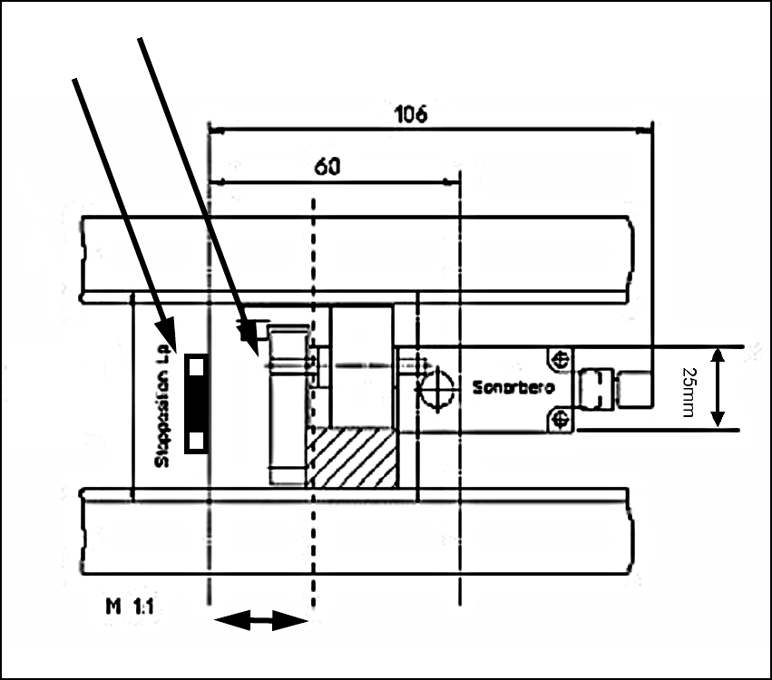
– For restrictions with respect to the installation area, see Fig. 107.
12.3 Notes
Do not adjust the throttles!
The throttles are preset correctly at the factory. Make sure you do not alter these settings!
Attention: Before the stopper is mounted in the machine, it should be adjusted with the guide strip
and the shims. Care should be taken to ensure that the stopper is not too loose or too tight. The
graduation of the shims is 0.1mm.
(See also Fig. 209, page - 232.) 12
12
Installation: 12
– If you use cable ties, remember to cut off the protruding ends.
– Be careful not to put a kink in hoses and cables. Always lay cables so that they do not impede
the functioning of the lifting table and cannot be damaged when it is in operation.
– Shorten pneumatic hoses to a reasonable length if necessary.
– Surfaces on which self-adhesive cable clamps, solenoid valves, etc., are to be stuck later
should be cleaned first with a lint-free cloth moistened with ethyl alcohol.
Assembly Instructions PCB Stopper Single Conveyor SIPLACE S-27HM / HS-60 / D4 / D3 / HF- / X-Series
Edition 06/2007
132
12.4 General
12.4.1 Stopper dimensions
Fig. 107 Stopper dimensions
Pivot unit
Stopper
Lifting table plate shortened by 27 mm
52 mm