NR_Mechanischer_Stopper.pdf - 第133页
Assembly Instructions PCB Stopper Single Conveyor SIPLACE S-27HM / HS-60 / D4 / D 3 / HF- / X-Series Edition 06/2007 133 12.4.2 Overview of conveyor sid es, locations, calibration pocket s Fig. 108 Overview of conveyor s…
Assembly Instructions PCB Stopper Single Conveyor SIPLACE S-27HM / HS-60 / D4 / D3 / HF- / X-Series
Edition 06/2007
132
12.4 General
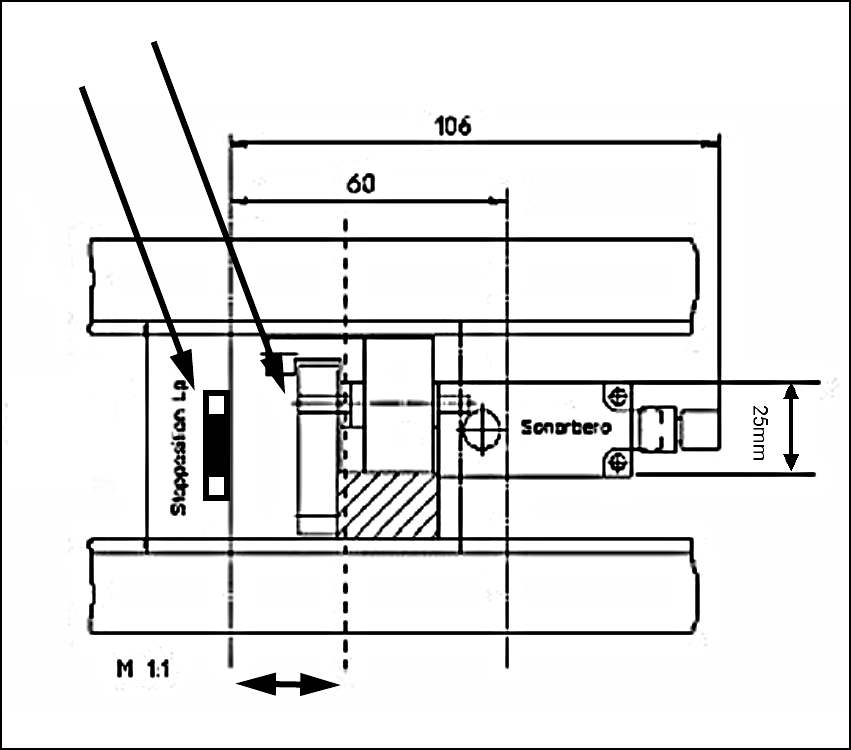
12.4.1 Stopper dimensions
Fig. 107 Stopper dimensions
Pivot unit
Stopper
Lifting table plate shortened by 27 mm
52 mm
Assembly Instructions PCB Stopper Single Conveyor SIPLACE S-27HM / HS-60 / D4 / D3 / HF- / X-Series
Edition 06/2007
133
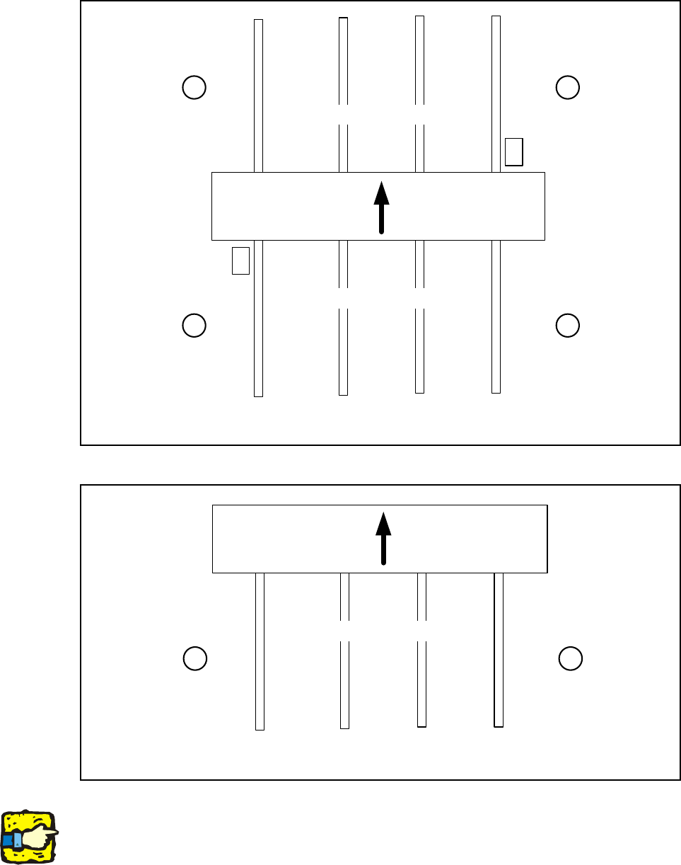
12.4.2 Overview of conveyor sides, locations, calibration pockets
Fig. 108 Overview of conveyor sides (HF, HF3, HS 60, D4, D3, X-Series)
Fig. 109 Overview of conveyor sides (S-27)
Note:
The calibration pocket is located in the middle of conveyor track 1 on the S-27.
1
23
4
Location Location
Location Location
Placement area 2
Placement area 1
Conveyor sides
4321
Calibration
pocket
Calibration
pocket
Transport
direction
12
Location Location
Placement area
Conveyor sides
4321
Transport
direction
Assembly Instructions PCB Stopper Single Conveyor SIPLACE S-27HM / HS-60 / D4 / D3 / HF- / X-Series
Edition 06/2007
134
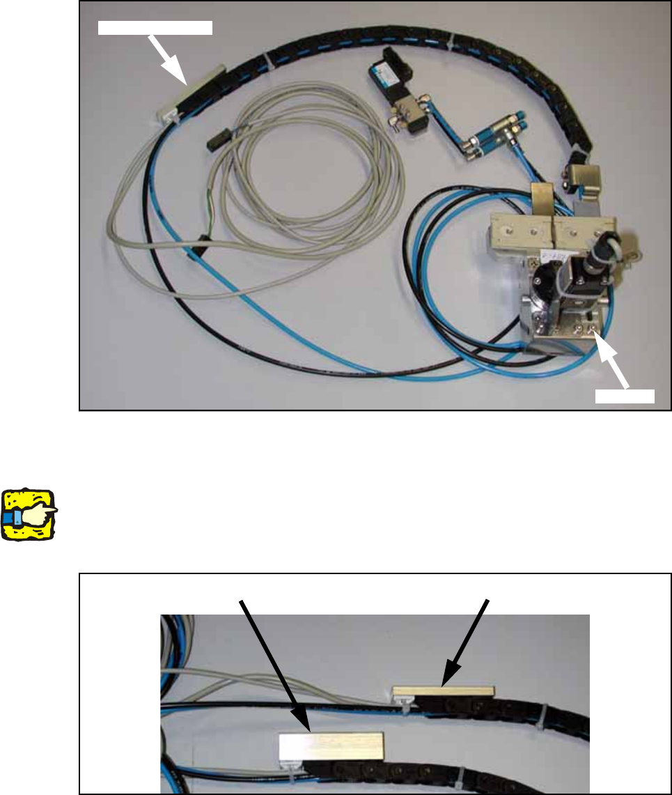
12.4.3 Overview of stopper
Fig. 110 Overview of stopper
12.4.3.1 High and low distance blocks
Note:
A distance block is screwed onto the loose end of the trailing cable. The height of this spacer var-
ies depending on the conveyor track and is stuck onto the floor of the mounting tub with adhesive
tape.
Fig. 111 High and low distance blocks
Distance block
Stopper
Low distance block
High distance block