NR_Mechanischer_Stopper.pdf - 第138页
Assembly Instructions PCB Stopper Sin gle Conveyor SIPLACE S-27HM / HS-60 / D4 / D3 / HF- / X-Series Edition 06/2007 138 12.6 Prep aratory work 12.6.1 Prep aring and terminating pneumati c hoses (HF , HF3, HS 60, D4, D3,…

Assembly Instructions PCB Stopper Single Conveyor SIPLACE S-27HM / HS-60 / D4 / D3 / HF- / X-Series
Edition 06/2007
137
12.5.3 Holders and screws for the guide strips
The holders for the guide strips differ according to the individual machines and placement areas.12
– Screws for the guide strip:
ISO 4762 - M5 x 20-8.8, chem. nickel plat. DIN 912 - M5 x 20-A2-70
"Cylinder head bolt with hexagon socket head M5 x 20"
12
Machine Designation Length Art.No. Screws for holders
S-27HM
Holder for
guide strip
S27 12
54 mm
03037444-
XX
DIN 912 - M4 x 40-A2-70 "Cylinder
head bolt with hexagon socket head
M4 x 40"
HS-60,
D4
Holder 1
guide strip
PA1 HS 12
24 mm
03032233-
XX
DIN 912 - M4 x 16-8.8 "Cylinder
head bolt with hexagon socket head
M4 x 16"
Holder 2
guide strip
PA2 HS 12
28 mm
03036928-
XX
DIN 912 - M4 x 16-8.8 "Cylinder
head bolt with hexagon socket head
M4 x 16"
HF-,
X-Series,
D3
Holder
guide strip
PA1 HF 12
49.5 mm
03032321-
XX
ISO 4762 - M4 x 40-8.8,
chem. nickel plat."Cylinder head bolt
with hexagon socket head M5 x 40"
Holder
guide strip
PA2 HF 12
65.5 mm
03032320-
XX
ISO 4762 - M4 x 40-8.8,
chem. nickel plat. "Cylinder head bolt
with hexagon socket head M5 x 40"
Tab. 12. 114 Holders for guide strips
Assembly Instructions PCB Stopper Single Conveyor SIPLACE S-27HM / HS-60 / D4 / D3 / HF- / X-Series
Edition 06/2007
138
12.6 Preparatory work
12.6.1 Preparing and terminating pneumatic hoses (HF, HF3, HS 60, D4, D3, X-
Series)
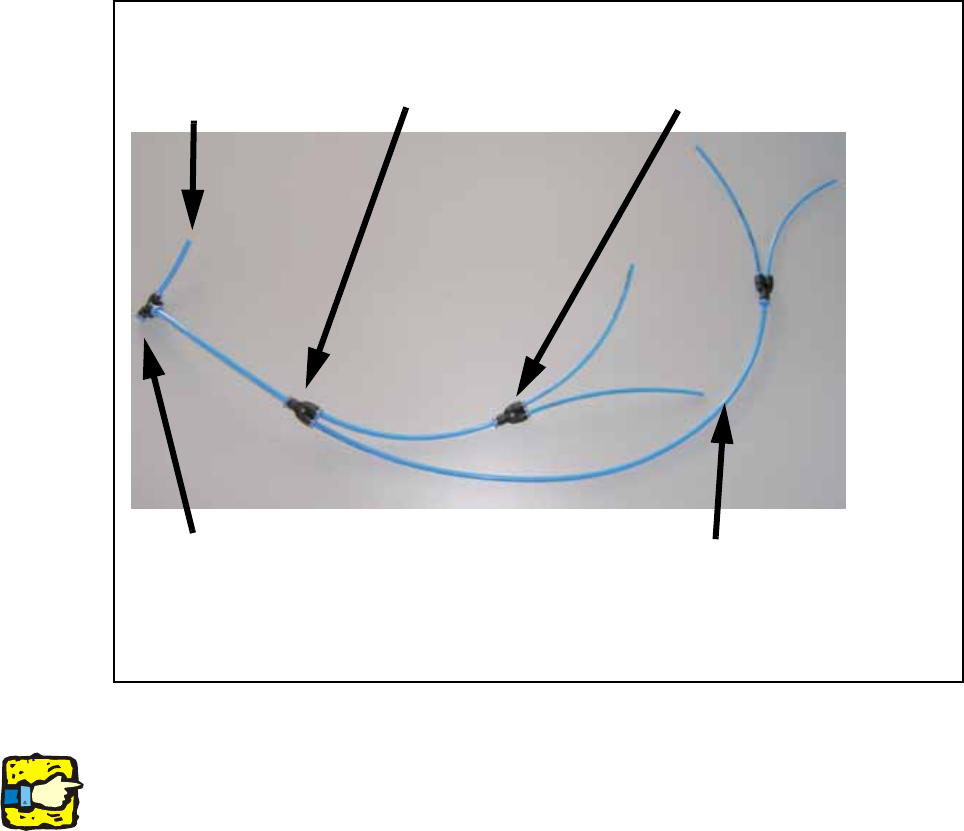
O Configure the pneumatic hoses as shown in the following figure.
Fig. 115 Overview of pneumatic hoses (HF, HF3, HS 60, D4, D3, X-Series)
Note for single conveyor
With a single conveyor only one PUN 3 hose is required in each case. The two unneeded con-
nections are each closed with a blind plug.
150mm PUN 4 hose with
Y-distributor
150 mm PUN 4 hose with Y-dis-
tributor to 2 x 150 mm PUN 3
hose to the solenoid valve PA1
40 mm PUN 4
hose to com-
pressed air sup-
ply
450 mm PUN 4 hose with Y-distributor
to 2 x 150 mm PUN 3 hose to the sole-
noid valve PA2
hose for width
adjustment
Assembly Instructions PCB Stopper Single Conveyor SIPLACE S-27HM / HS-60 / D4 / D3 / HF- / X-Series
Edition 06/2007
139
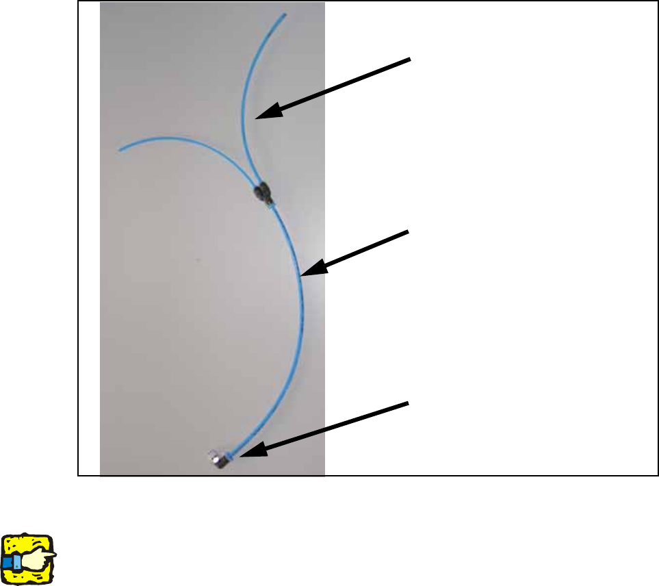
12.6.2 Preparing and terminating pneumatic hoses (S-27HM)
O Configure the pneumatic hoses as shown in the following figure.
Fig. 116 Overview of pneumatic hoses (S-27HM)
Note for single conveyor
With a single conveyor only one PUN 3 hose is required. The unneeded connection is closed
with a blind plug.
4-fold distributor PUN 6 to 4 x PUN 4
with PUN 4 hose to compressed air
supply and PUN 6 plug
200 mm PUN 4 hose to compressed
air supply, width
adjustment
2 x 200 mm PUN 3hose with Y-distrib-
utor to 2 x 100 mm PUN 3 hose to the
solenoid valve PA2