NR_Mechanischer_Stopper.pdf - 第139页
Assembly Instructions PCB Stopper Single Conveyor SIPLACE S-27HM / HS-60 / D4 / D 3 / HF- / X-Series Edition 06/2007 139 12.6.2 Prep aring and terminat ing pneumatic hoses (S-27HM) O Configure th e pneumatic hoses as sho…
Assembly Instructions PCB Stopper Single Conveyor SIPLACE S-27HM / HS-60 / D4 / D3 / HF- / X-Series
Edition 06/2007
138
12.6 Preparatory work
12.6.1 Preparing and terminating pneumatic hoses (HF, HF3, HS 60, D4, D3, X-
Series)
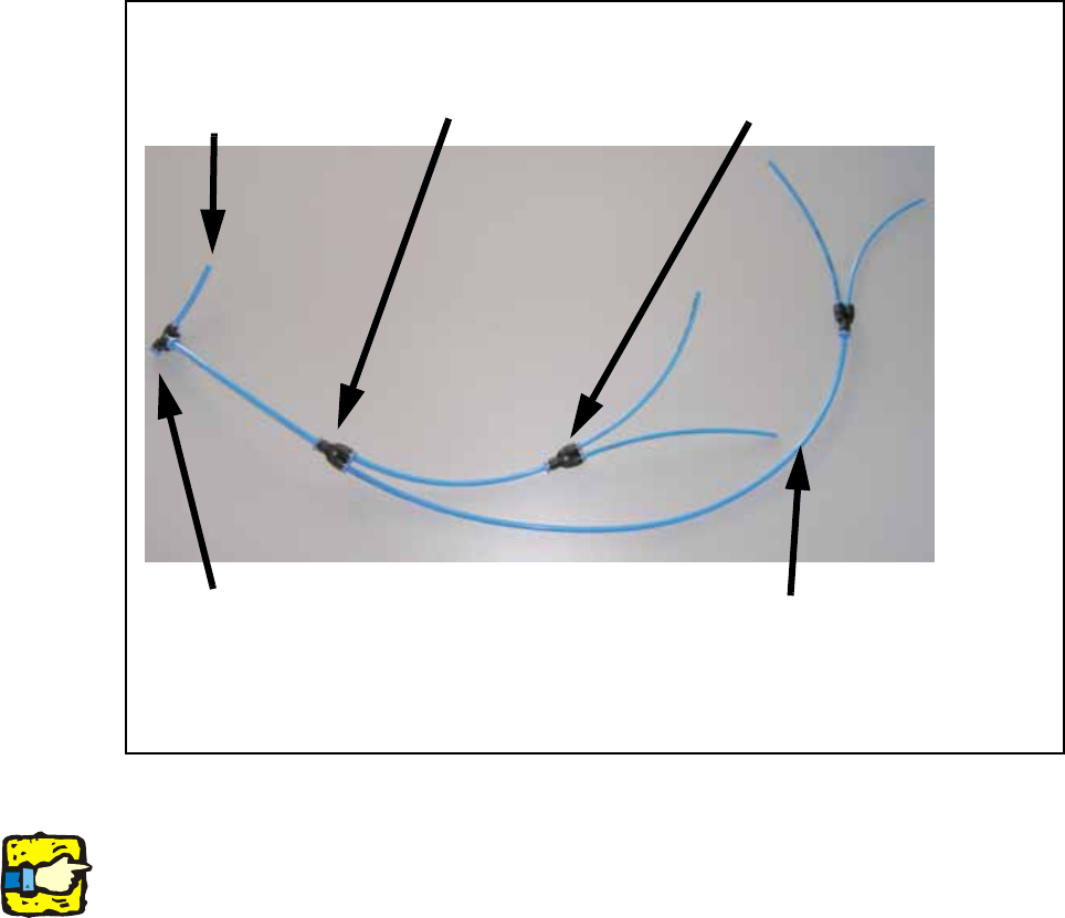
O Configure the pneumatic hoses as shown in the following figure.
Fig. 115 Overview of pneumatic hoses (HF, HF3, HS 60, D4, D3, X-Series)
Note for single conveyor
With a single conveyor only one PUN 3 hose is required in each case. The two unneeded con-
nections are each closed with a blind plug.
150mm PUN 4 hose with
Y-distributor
150 mm PUN 4 hose with Y-dis-
tributor to 2 x 150 mm PUN 3
hose to the solenoid valve PA1
40 mm PUN 4
hose to com-
pressed air sup-
ply
450 mm PUN 4 hose with Y-distributor
to 2 x 150 mm PUN 3 hose to the sole-
noid valve PA2
hose for width
adjustment
Assembly Instructions PCB Stopper Single Conveyor SIPLACE S-27HM / HS-60 / D4 / D3 / HF- / X-Series
Edition 06/2007
139
12.6.2 Preparing and terminating pneumatic hoses (S-27HM)
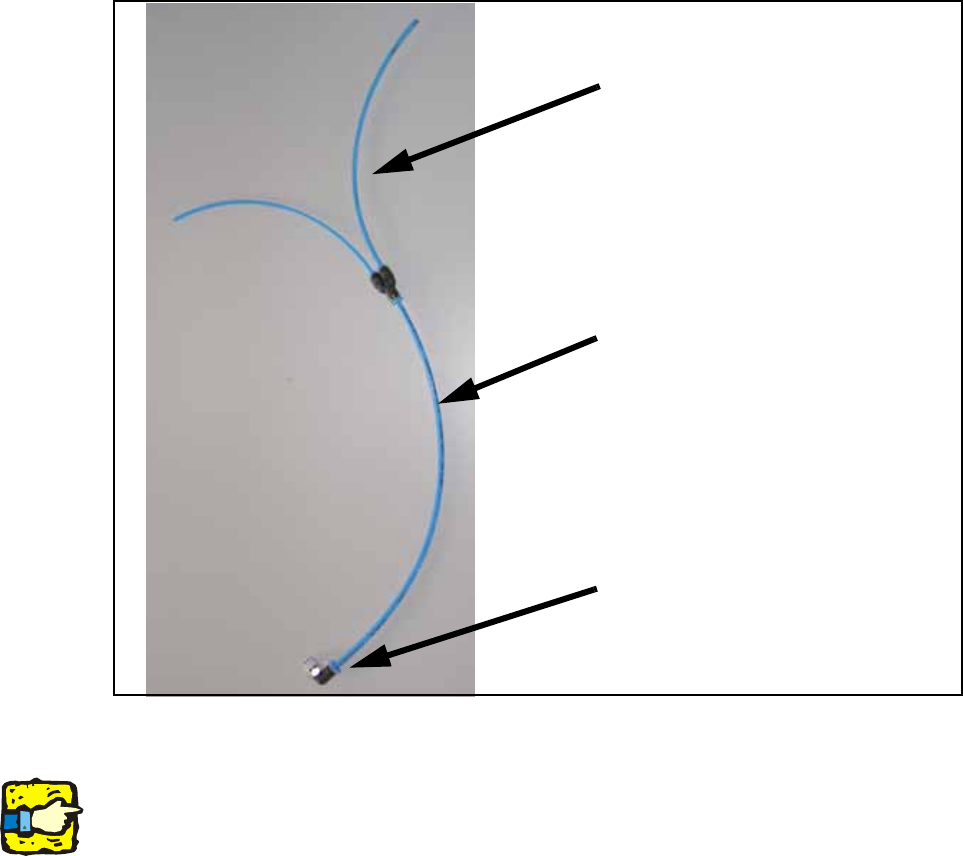
O Configure the pneumatic hoses as shown in the following figure.
Fig. 116 Overview of pneumatic hoses (S-27HM)
Note for single conveyor
With a single conveyor only one PUN 3 hose is required. The unneeded connection is closed
with a blind plug.
4-fold distributor PUN 6 to 4 x PUN 4
with PUN 4 hose to compressed air
supply and PUN 6 plug
200 mm PUN 4 hose to compressed
air supply, width
adjustment
2 x 200 mm PUN 3hose with Y-distrib-
utor to 2 x 100 mm PUN 3 hose to the
solenoid valve PA2
Assembly Instructions PCB Stopper Single Conveyor SIPLACE S-27HM / HS-60 / D4 / D3 / HF- / X-Series
Edition 06/2007
140
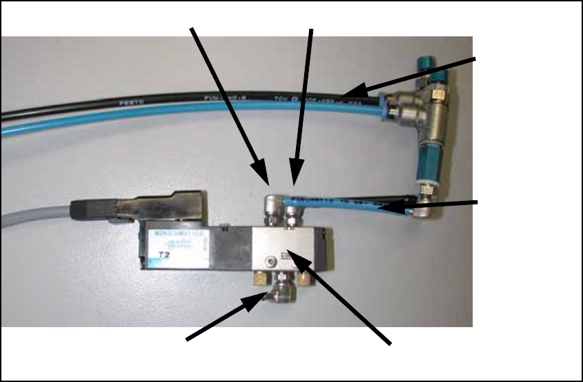
12.6.3 Connection of pneumatic lines
O Connect the two air lines of the rotating cylinder to the two solenoid valves of the pneumatic
valve unit.
The blue line is linked to connection 4, the black line to connection 2.
Fig. 117 Connection of pneumatic lines
Connection 4 Connection 2
Black = Connec-
tion to rotating
cylinder
Insert stopper
with adjustable
throttle
Blue = Connec-
tion to rotating
cylinder
Withdraw stop-
per with adjust-
able throttle
Compressed air
supply
Solenoid valve