NR_Mechanischer_Stopper.pdf - 第144页
Assembly Instructions PCB Stopper Sin gle Conveyor SIPLACE S-27HM / HS-60 / D4 / D3 / HF- / X-Series Edition 06/2007 144 13.1.1 Overview Fig. 1 18 Overview HS-60, D4 (Fig. 1) Single co nveyor

Assembly Instructions PCB Stopper Single Conveyor SIPLACE S-27HM / HS-60 / D4 / D3 / HF- / X-Series
Edition 06/2007
143
13 Retrofitting SIPLACE HS-60 / D4
13.1 Preparatory work
Caution: Before the stopper is mounted in the machine, it should be adjusted with the guide strip
and the shims. Care should be taken to ensure that the stopper is not too loose or too tight. The
graduation of the shims is 0.1mm.
(See also Fig. 209, page - 232.) 13
13
O Change over to the SITEST.
O Select "Conveyor" and "Conveyor width".
O For a single conveyor, set the conveyor width to maximum.
O For a dual conveyor set the conveyor width as follows:
O Shut down the operating system and switch off the placement machine at the main switch.
O Remove the plates of the lifting table and the cover over the conversion board for the PCB con-
veyor.
O Remove the cover of conversion board.
O Remove the metal cover of the cable ducts.
O Remove the cable duct covers.
In placement area 2 the lifting table needs to be moved back 20 mm.
So start the rest of the conversion in placement area 2.
O On dual conveyor machines, remove the following nozzle changers:
– Conveyor left: Nozzle changer at location 2
– Conveyor right: Nozzle changer at location 3
Fixed conveyor left Conveyor track 1: 50 mm Conveyor track 2: 200 mm
Fixed conveyor right Conveyor track 1: Max. width Conveyor track 2: 50 mm
Assembly Instructions PCB Stopper Single Conveyor SIPLACE S-27HM / HS-60 / D4 / D3 / HF- / X-Series
Edition 06/2007
144
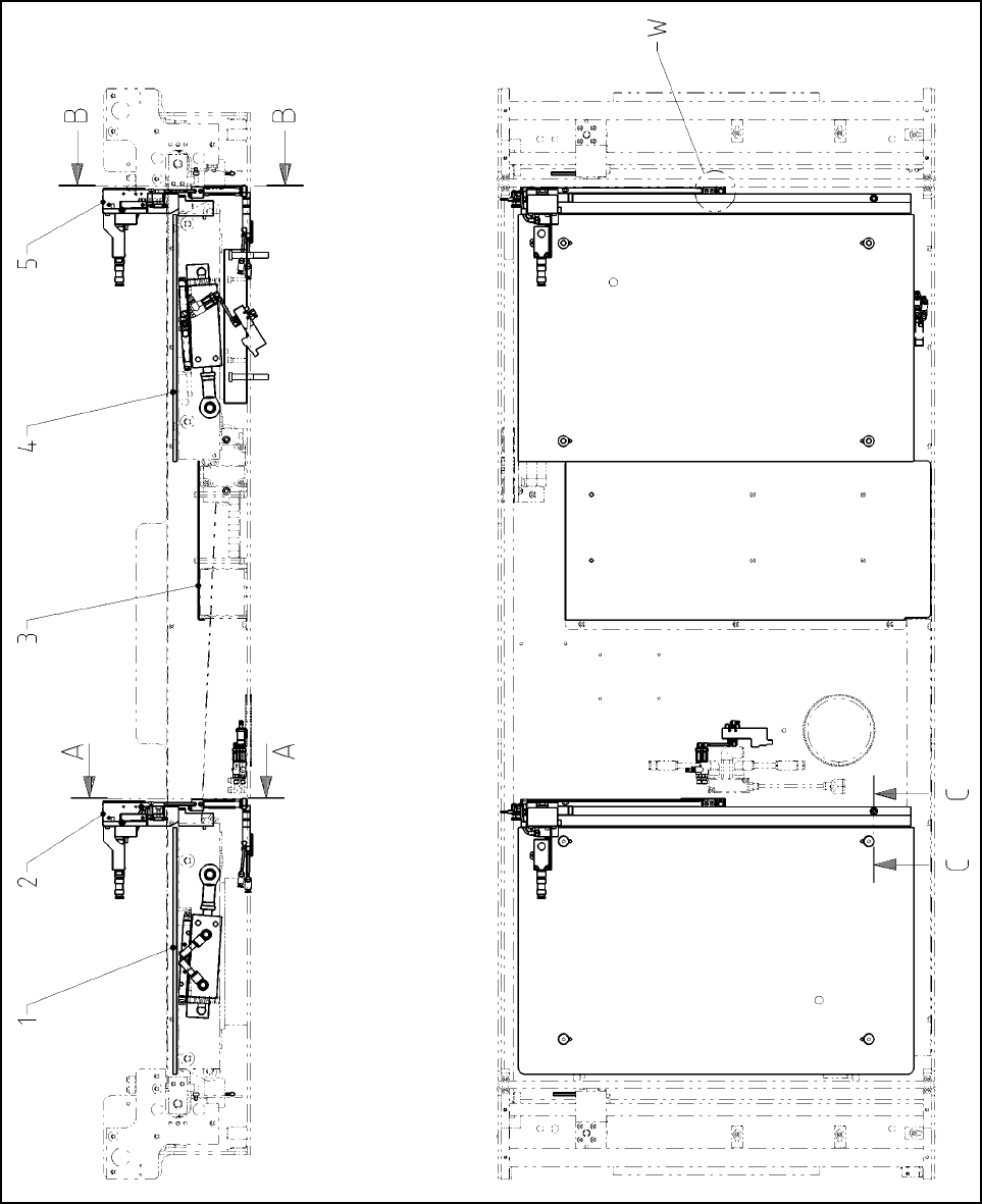
13.1.1 Overview
Fig. 118 Overview HS-60, D4 (Fig. 1) Single conveyor
Assembly Instructions PCB Stopper Single Conveyor SIPLACE S-27HM / HS-60 / D4 / D3 / HF- / X-Series
Edition 06/2007
145
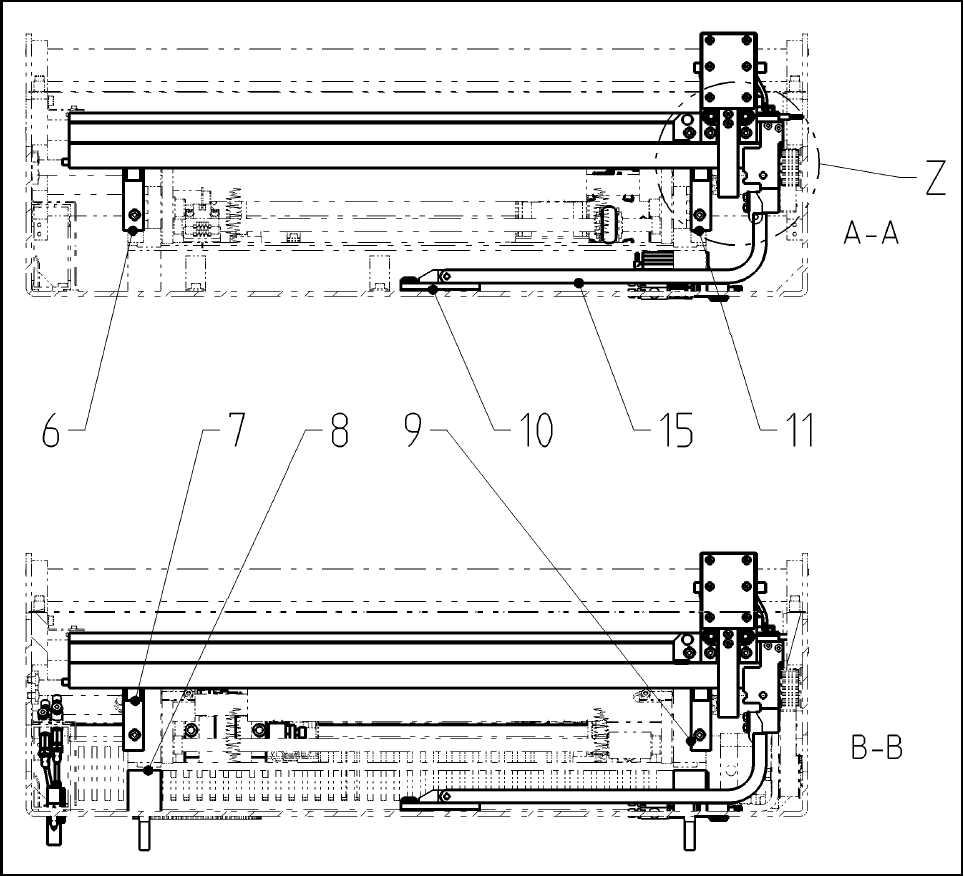
Fig. 119 Overview HS-60, D4 (Fig. 2) Single conveyor
Legend (Figs. 1 and 2) Single conveyor
1
Plate of lifting table PA1 HS SC Opt. Stopper
10
Distance block for energy chain, compl.
2
Basic unit stopper HS/HF PA1
11
Holder 2 guide strip PA1 HS
3
Cover of conversion board Opt. Stopper
12
DIN EN ISO 7380-M3 x 6-A2
4
Plate of lifting table Opt. Stopper HS SC PA2
13
Energy chain holder
5
Basic unit stopper HS/HF PA2
14
ISO 4032 - M3-8
6
Holder 1 guide strip PA1 HS
15
Energy chain E04
7
Holder 2 guide strip PA2 HS
16
Guide strip HS
8
Distance piece for lifting table (option)
17
ISO 4762 - M 5 x 20-8.8, chem. nickel
plat.
9
Holder 1 guide strip PA2 HS
18
DIN912-M4 x 16-8.8