NR_Mechanischer_Stopper.pdf - 第147页
Assembly Instructions PCB Stopper Single Conveyor SIPLACE S-27HM / HS-60 / D4 / D 3 / HF- / X-Series Edition 06/2007 147 Fig. 121 Overview HS-60, D4 (Fig. 4) Dual conveyor Legend Dual conveyor (Figs. 3 and 4) 13 1 Plate …
Assembly Instructions PCB Stopper Single Conveyor SIPLACE S-27HM / HS-60 / D4 / D3 / HF- / X-Series
Edition 06/2007
146
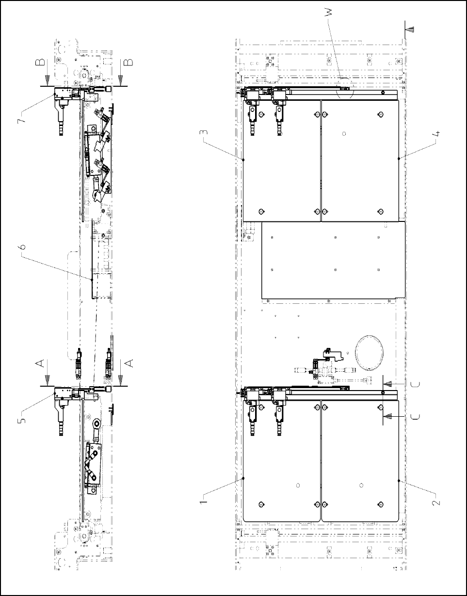
Fig. 120 Overview HS-60, D4 (Fig. 3) Dual conveyor
Assembly Instructions PCB Stopper Single Conveyor SIPLACE S-27HM / HS-60 / D4 / D3 / HF- / X-Series
Edition 06/2007
147
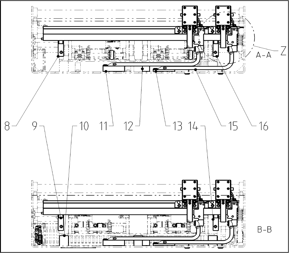
Fig. 121 Overview HS-60, D4 (Fig. 4) Dual conveyor
Legend Dual conveyor (Figs. 3 and 4) 13
1
Plate of lifting table Opt. Stopper HS DC PA1 SP1
12
Distance block for energy chain, compl.
2
Plate of lifting table Opt. Stopper HS DC PA1 SP2
13
Distance piece complete
3
Plate of lifting table Opt. Stopper HS DC PA2 SP1
14
Holder 1 guide strip PA2 HS
4
Plate of lifting table Opt. Stopper HS DC PA2 SP2
15
Energy chain E04
5
Basic unit stopper HS/HF PA1
16
Holder 2 guide strip PA1 HS
6
Cover of conversion board Opt. Stopper
17
Guide strip HS
7
Basic unit stopper HS/HF PA2
18
ISO 4762 - M 5 x 20-8.8, chem. nickel plat.
8
Holder 1 guide strip PA1 HS
19
DIN912-M4 x 16-8.8
9
Holder 2 guide strip PA2 HS
20
DIN EN ISO 7380-M3 x 6-A2
10
Distance piece for lifting table (option)
21
Energy chain holder
11
Distance block for energy chain, compl.
22
ISO 4032 - M3-8
Assembly Instructions PCB Stopper Single Conveyor SIPLACE S-27HM / HS-60 / D4 / D3 / HF- / X-Series
Edition 06/2007
148
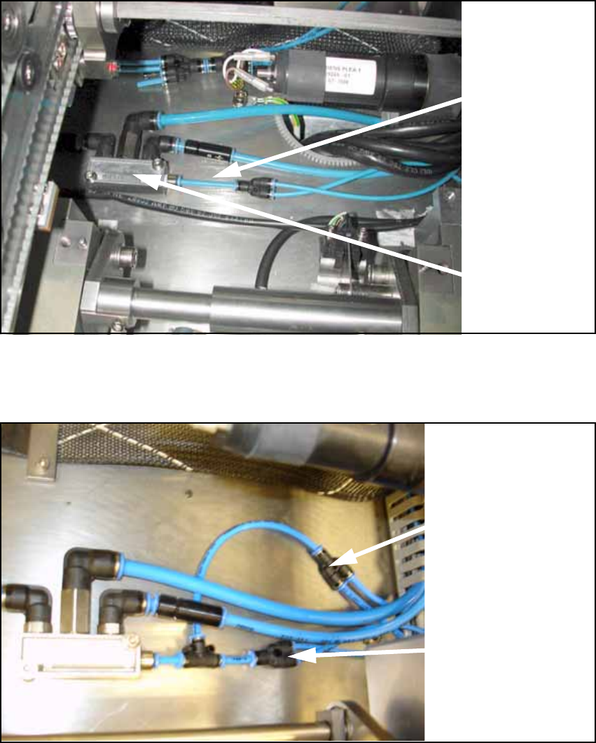
13.1.2 Preparation of pneumatics
O Detach the supply hose (PUN 4) for width adjustment.
Fig. 122
O Connect the prepared hoses to the conveyor pneumatic distributor as shown in the following
figure.
Fig. 123
13
Supply
hose (PUN 4)
for width
adjustment
Pneumatic
distributor
Supply hose (PUN 4)
for width adjustment
Supply hose (PUN 4)
for stopper unit