NR_Mechanischer_Stopper.pdf - 第149页
Assembly Instructions PCB Stopper Single Conveyor SIPLACE S-27HM / HS-60 / D4 / D 3 / HF- / X-Series Edition 06/2007 149 13.2 Inst allation at placement area 2 13.2.1 Inst all dist ance pieces and holders O Only if fixed…
Assembly Instructions PCB Stopper Single Conveyor SIPLACE S-27HM / HS-60 / D4 / D3 / HF- / X-Series
Edition 06/2007
148
13.1.2 Preparation of pneumatics
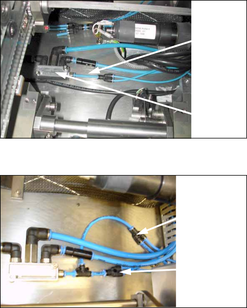
O Detach the supply hose (PUN 4) for width adjustment.
Fig. 122
O Connect the prepared hoses to the conveyor pneumatic distributor as shown in the following
figure.
Fig. 123
13
Supply
hose (PUN 4)
for width
adjustment
Pneumatic
distributor
Supply hose (PUN 4)
for width adjustment
Supply hose (PUN 4)
for stopper unit
Assembly Instructions PCB Stopper Single Conveyor SIPLACE S-27HM / HS-60 / D4 / D3 / HF- / X-Series
Edition 06/2007
149
13.2 Installation at placement area 2
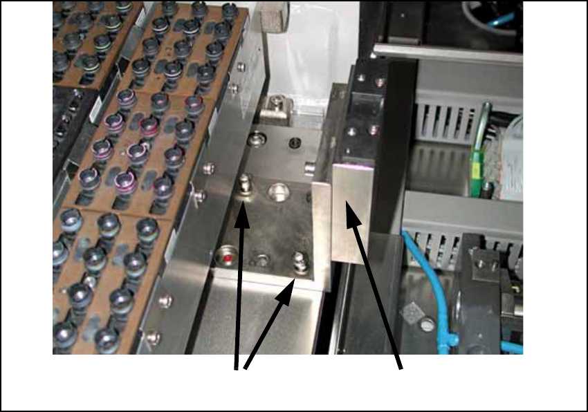
13.2.1 Install distance pieces and holders
O Only if fixed conveyor side on the left:
Remove the holder for the machine zero point (2 screws).
Note the current position of the holder. This is pinned and can be installed in two different ways.
The holder must be reinstalled later in the same position. So if necessary mark the position
with a pen.
Fig. 124
13
13
13
2 screws
Holder for machine zero point
Assembly Instructions PCB Stopper Single Conveyor SIPLACE S-27HM / HS-60 / D4 / D3 / HF- / X-Series
Edition 06/2007
150
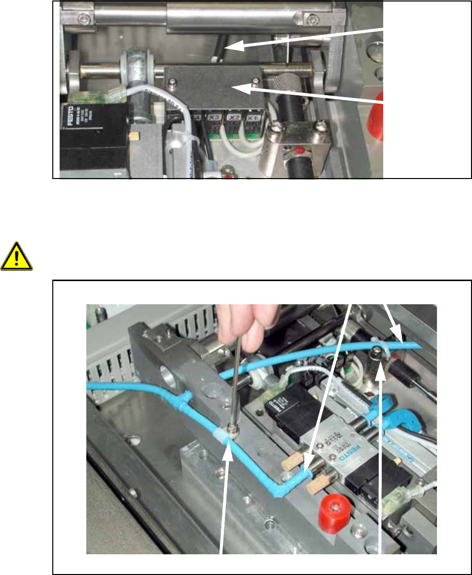
O Unscrew the cover of the lifting table board (see the following figure).
O Detach the control cable with the connector designation X6 on the lifting table board.
Fig. 125
O Detach the cable clamp and the cable tie and pull the pneumatic hose off the lifting table mech-
anism from both sides.
13
13
13
13
Be careful not to damage hoses or cables! 13
Fig. 126
Control cable
Cover of
lifting table
board
Detach cable clamp Detach cable tie
Remove hose