NR_Mechanischer_Stopper.pdf - 第151页
Assembly Instructions PCB Stopper Single Conveyor SIPLACE S-27HM / HS-60 / D4 / D 3 / HF- / X-Series Edition 06/2007 151 O Unscrew the fastening screws of the lifting table marked in Fig. 127 (M8 x 120 mm (blue) / M6 x 8…
Assembly Instructions PCB Stopper Single Conveyor SIPLACE S-27HM / HS-60 / D4 / D3 / HF- / X-Series
Edition 06/2007
150
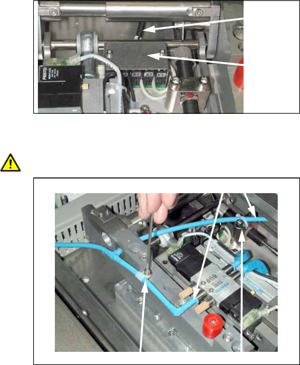
O Unscrew the cover of the lifting table board (see the following figure).
O Detach the control cable with the connector designation X6 on the lifting table board.
Fig. 125
O Detach the cable clamp and the cable tie and pull the pneumatic hose off the lifting table mech-
anism from both sides.
13
13
13
13
Be careful not to damage hoses or cables! 13
Fig. 126
Control cable
Cover of
lifting table
board
Detach cable clamp Detach cable tie
Remove hose
Assembly Instructions PCB Stopper Single Conveyor SIPLACE S-27HM / HS-60 / D4 / D3 / HF- / X-Series
Edition 06/2007
151
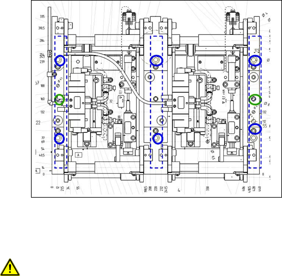
O Unscrew the fastening screws of the lifting table marked in Fig. 127 (M8 x 120 mm (blue) / M6
x 80 mm (green)) and lift the lifting table carefully out of the conveyor.
13
Fig. 127 Fastening screws of lifting table
On a single conveyor the lifting table can be lifted out between the conveyor sides. 13
On a dual conveyor the lifting table must be lifted out toward location 2 in the case of left conveyor
and toward location 3 in the case of right conveyor. 13
13
Caution: The lifting table is very heavy (approx. 12 kg). 13
Be careful not to damage the lifting table or the underside of the conveyor! 13
13
Assembly Instructions PCB Stopper Single Conveyor SIPLACE S-27HM / HS-60 / D4 / D3 / HF- / X-Series
Edition 06/2007
152
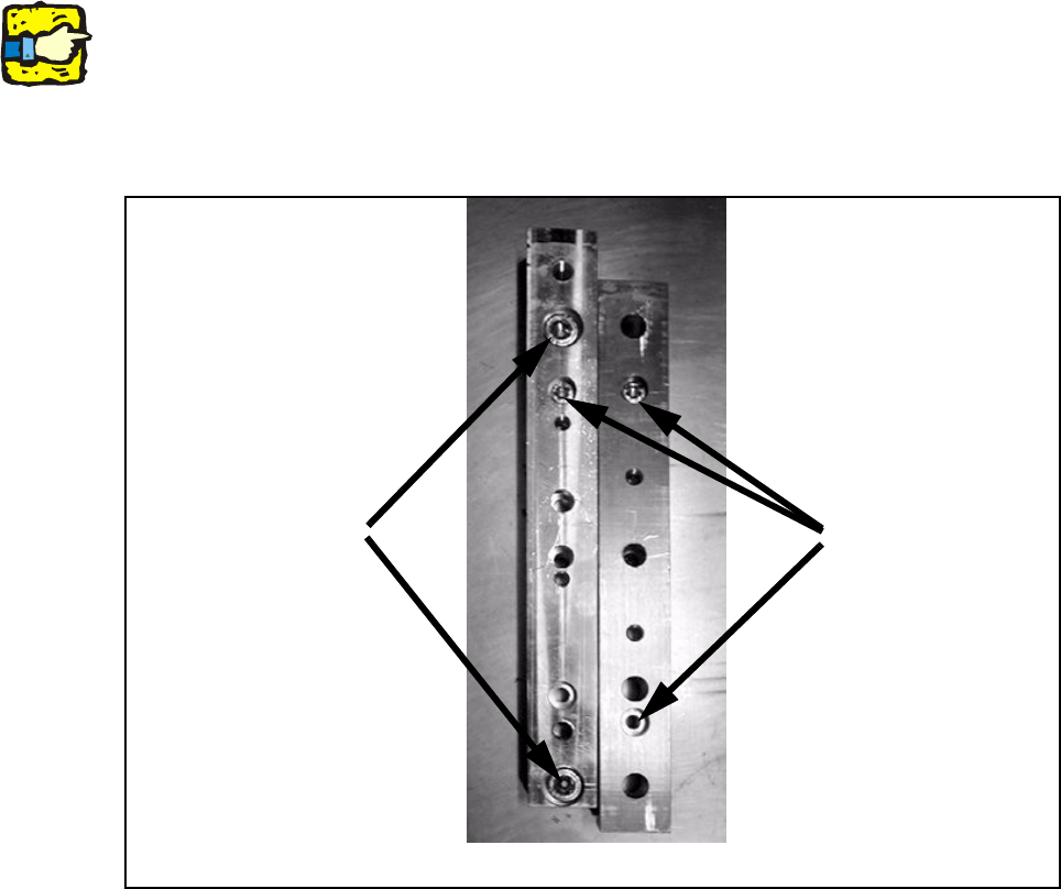
O Remove the distance pieces and replace them with the optional distance pieces [03040964-
xx] (single conveyor 2 pcs. / dual conveyor 3 pcs.).
To do this, use one screw from the original distance piece to pre-position each new piece and
two M8 x 50 - DIN 6912 to fasten it.
For the single conveyor 2 distance pieces must be exchanged here, and for the dual conveyor
3 distance pieces.
13
13
The new distance pieces must be parallel when installed in the conveyor tub so that the alignment
pins of the lifting table can be easily sunk into the new distance pieces.
If they are not already preassembled on the distance piece, use the supplied alignment pins for
this. 13
13
Fig. 128 Distance pieces
M6x50 mm
M8x50 mm
Optional distance piece
[03040964-xx]
New (left) and old (right) distance piece