NR_Mechanischer_Stopper.pdf - 第155页
Assembly Instructions PCB Stopper Single Conveyor SIPLACE S-27HM / HS-60 / D4 / D 3 / HF- / X-Series Edition 06/2007 155 O Screw the lifting table onto the distance pieces, as shown in the graphic, with six (for dual con…
Assembly Instructions PCB Stopper Single Conveyor SIPLACE S-27HM / HS-60 / D4 / D3 / HF- / X-Series
Edition 06/2007
154
O Clean the conveyor tub in the area of the conveyor width adjustment with a lint-free cloth moist-
ened with ethyl alcohol.
The tub should be free of grease as the trailing cables are to be fastened here with double-
sided adhesive tape.
13
13
When you place the lifting table back in the conveyor, be careful not to damage either the con-
veyor, the lifting table (forked light barrier) or cables/hoses. 13
13
O Insert the lifting table. Place it on the distance pieces.
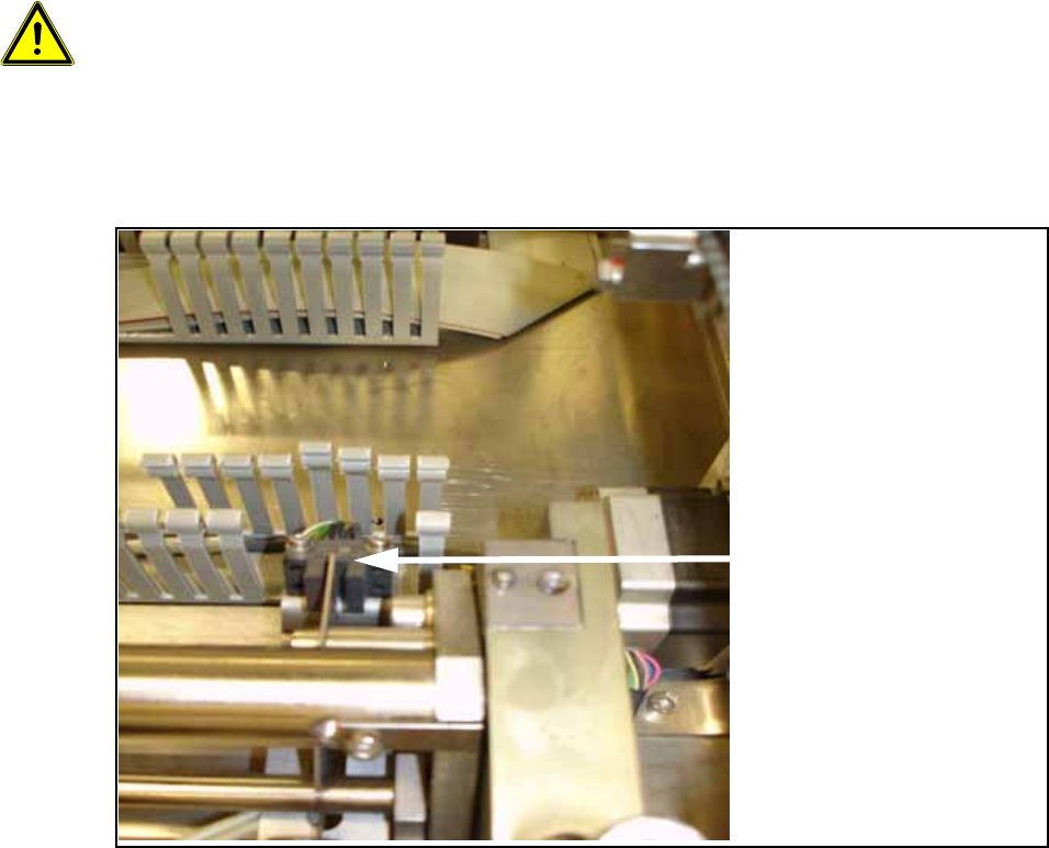
O Remove 3 to 4 segments of the cable duct in the area of the lifting table's forked light barriers.
O Detach the cable clamp for the control cable of the lifting table.
Remove 3 to 4
segments for the forked
light barriers.
Assembly Instructions PCB Stopper Single Conveyor SIPLACE S-27HM / HS-60 / D4 / D3 / HF- / X-Series
Edition 06/2007
155
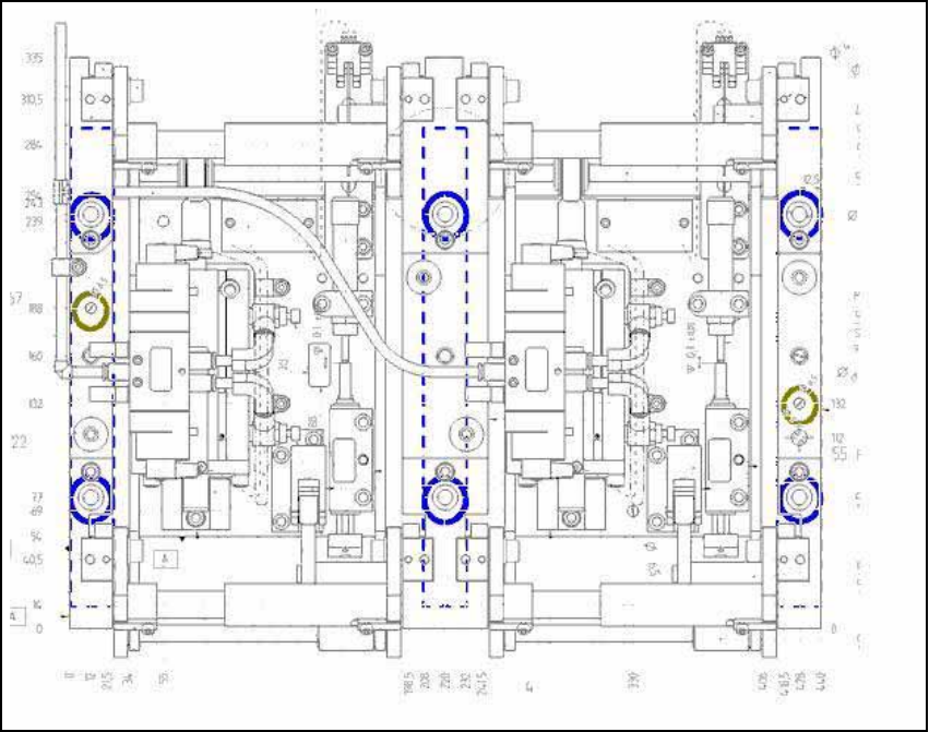
O Screw the lifting table onto the distance pieces, as shown in the graphic, with six (for dual con-
veyor) or four (for single conveyor) M8 x 70 mm screws (see figure, blue) and two M6 x 80 mm
screws (green).
Fig. 131 Fastening screws of lifting table
Assembly Instructions PCB Stopper Single Conveyor SIPLACE S-27HM / HS-60 / D4 / D3 / HF- / X-Series
Edition 06/2007
156
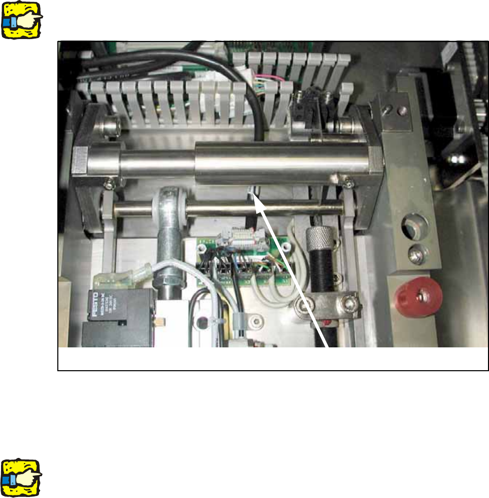
O Connect the control cable and the compressed air hose to the lifting table again.
13
13
When doing so make sure that the cable is laid beneath the mechanical system.
13
Fig. 132
O Install the cover over the lifting table board.
13
For dual conveyor only: 13
Remove all parts from the machine that are not permanently attached to it (tools and other parts
required for the installation).
Don't forget the nozzle changer and the machine zero point. 13
O Switch the machine on again at the main switch.
O Carry out a reference run and change the conveyor track setting from 50 mm to maximum con-
veyor width.
O Shut down the operating system and switch off the placement machine at the main switch.
Cable