NR_Mechanischer_Stopper.pdf - 第159页
Assembly Instructions PCB Stopper Single Conveyor SIPLACE S-27HM / HS-60 / D4 / D 3 / HF- / X-Series Edition 06/2007 159 O Using the prep ared adhesive ta pe, stick the trailing cable dist ance block onto the mounting tr…
Assembly Instructions PCB Stopper Single Conveyor SIPLACE S-27HM / HS-60 / D4 / D3 / HF- / X-Series
Edition 06/2007
158
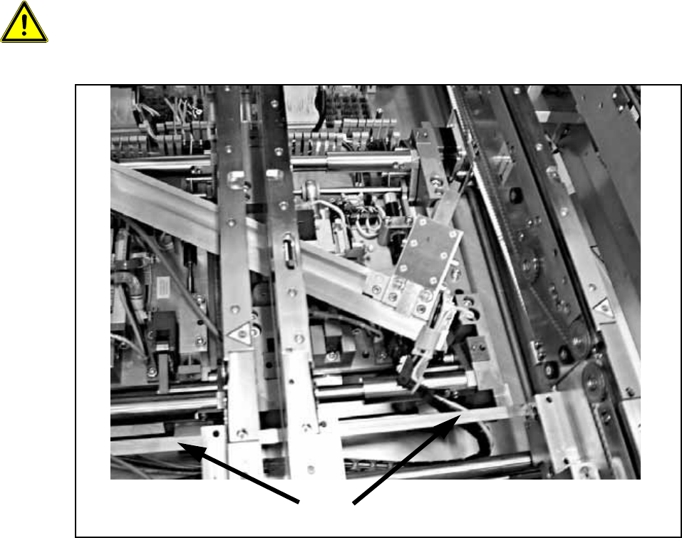
O Insert the two stopper units between the two side sections into the guide slot of the guide strip.
13
When installing the stopper be careful not to damage the terminal strip of the width adjustment for
the PCB conveyor. 13
13
Fig. 134
Terminal strip of width adjustment for PCB conveyor
Assembly Instructions PCB Stopper Single Conveyor SIPLACE S-27HM / HS-60 / D4 / D3 / HF- / X-Series
Edition 06/2007
159
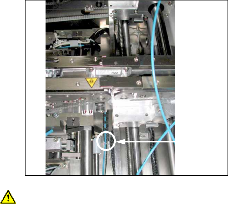
O Using the prepared adhesive tape, stick the trailing cable distance block onto the mounting
trough under the second conveyor side parallel to the guide rail (or to the width adjustment) in
such a way that the trailing cable stands vertical when the guide rail is installed.
O With a single conveyor, stick the holder onto the mounting tub under conveyor side 1.
O With a dual conveyor, the trailing cable of the first conveyor track must run on the trailing cable
of the second conveyor track.
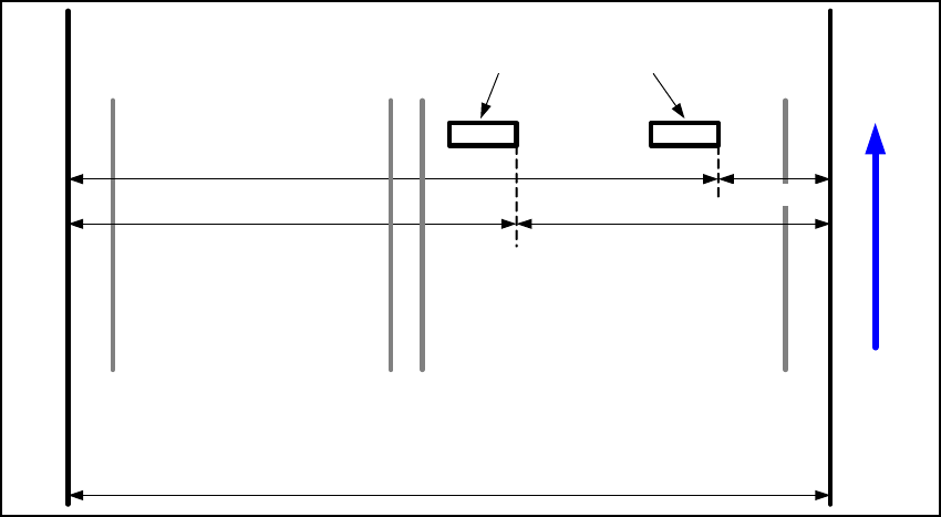
For HS-60 and D4 (mounting tub 587 mm) with dual and single conveyor, the following distances
must be observed: 13
Fig. 135 Positions of the distance blocks (HS-60, D4)
For a dual conveyor, stick an additional "Distance block for energy chain, complete" [03043432-
xx] in the middle between the two distance blocks for better movement of the trailing cable . 13
The stopper must be able to slide over the entire conveyor width. 13
The attachment on the floor of the mounting tub must be positioned so that the trailing cables run
parallel to the guide strip of the stopper.
If cables should prevent this, they must be repositioned. 13
Conveyor track 2 Conveyor track 1
Distance block for energy chain
Left
conveyor side
Right
conveyor side
340 mm 240 mm
440 mm 140 mm
Transport direction
Left side of
mounting tub
Right side of
mounting tub
587 mm
Assembly Instructions PCB Stopper Single Conveyor SIPLACE S-27HM / HS-60 / D4 / D3 / HF- / X-Series
Edition 06/2007
160
Fig. 136
13
Caution, crash hazard:
It is essential to ensure that the stopper and the trailing cables do not collide with the width adjust-
ment or its conveyor belt. 13
The stopper must subsequently move freely over the entire conveyor width, and the trailing cables
must not tilt to the side. 13
13
Stick here
Holder
Trailing cables