NR_Mechanischer_Stopper.pdf - 第163页
Assembly Instructions PCB Stopper Single Conveyor SIPLACE S-27HM / HS-60 / D4 / D 3 / HF- / X-Series Edition 06/2007 163 13.3 Inst allation at placement area 1 The description of the inst allation pro cess is based on th…
Assembly Instructions PCB Stopper Single Conveyor SIPLACE S-27HM / HS-60 / D4 / D3 / HF- / X-Series
Edition 06/2007
162
O Affix the guide strip to the holders with two cylinder head bolts with hexagon socket head
M5 x 20-DIN 912.
Fig. 139
O Check that the stoppers can move freely across the entire conveyor width and do not impede
the width adjustment of the conveyor in any way.
Cable laying and wiring are described in a later section for functional reasons. 13
13
Screws
Assembly Instructions PCB Stopper Single Conveyor SIPLACE S-27HM / HS-60 / D4 / D3 / HF- / X-Series
Edition 06/2007
163
13.3 Installation at placement area 1
The description of the installation process is based on the example of a dual conveyor. Single con-
veyor installation is carried out similarly.
13
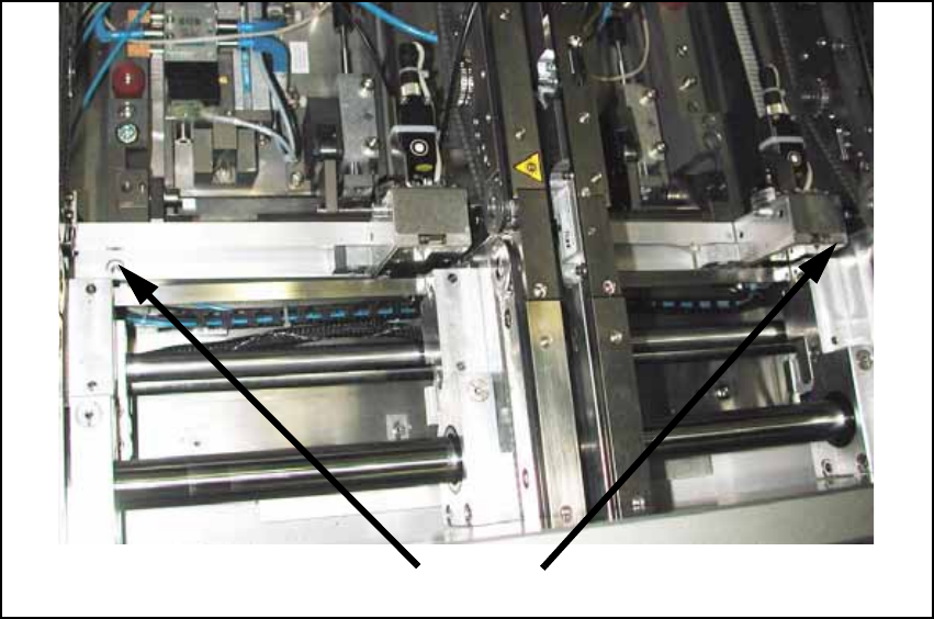
O In placement area 1, install holders 1 + 2 for the guide strip of the PCB stopper.
The holders are installed so that they are flush at the top with the lateral frames of the lifting
table. To prevent the holder from twisting, the lateral shoulder of the holder must lie against the
outside of the frames.
The holders are attached with one cylinder head bolt with hexagon socket head M4 x 16 -
DIN 912
Fig. 140
Holder of guide strip
Assembly Instructions PCB Stopper Single Conveyor SIPLACE S-27HM / HS-60 / D4 / D3 / HF- / X-Series
Edition 06/2007
164
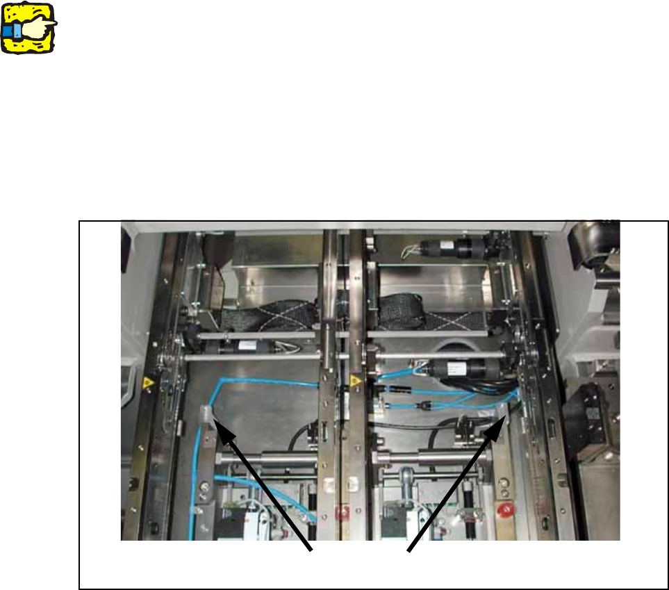
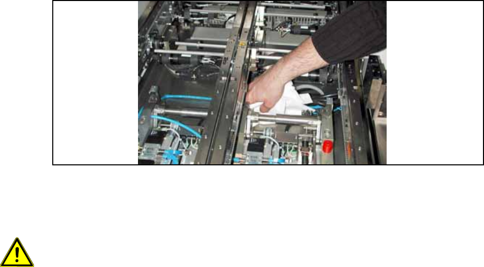
O Clean the conveyor tub in the area of the guide strip with a lint-free cloth moistened with ethyl
alcohol.
Fig. 141
O Relocate any cables that may run there.
13
Caution: Before the stopper is mounted in the machine, it should be adjusted with the guide strip
and the shims. Care should be taken to ensure that the stopper is not too loose or too tight. The
graduation of the shims is 0.1mm.
(See also Fig. 209, page - 232.) 13