NR_Mechanischer_Stopper.pdf - 第166页
Assembly Instructions PCB Stopper Sin gle Conveyor SIPLACE S-27HM / HS-60 / D4 / D3 / HF- / X-Series Edition 06/2007 166 O First attach the trailing cable distance block (fla t distance block) of conveyor track 2 on the …
Assembly Instructions PCB Stopper Single Conveyor SIPLACE S-27HM / HS-60 / D4 / D3 / HF- / X-Series
Edition 06/2007
165
O Before doing so, remove the cable tie with which the black cable is attached to the air distrib-
utor.
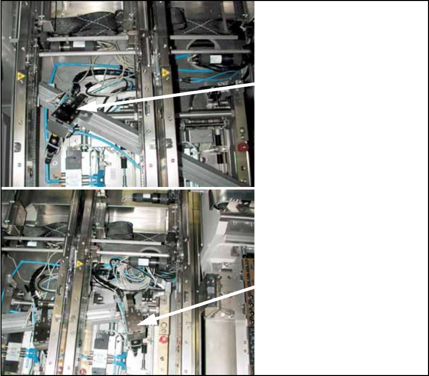
O Push the guide strip into the conveyor from outside.
Insert the stopper units carefully between the two side sections into the guide slot of the guide
strip.
Fig. 142
13
Stopper PA1
Conveyor track 2
Stopper PA1
Conveyor track 1
Assembly Instructions PCB Stopper Single Conveyor SIPLACE S-27HM / HS-60 / D4 / D3 / HF- / X-Series
Edition 06/2007
166
O First attach the trailing cable distance block (flat distance block) of conveyor track 2 on the
mounting tub. The distance block should be attached in the center under conveyor side 2 di-
rectly next to the main air distributor of the conveyor.
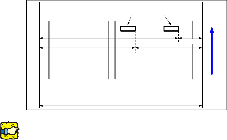
For HS-60 and D4 (mounting tub 587 mm) with dual and single conveyor, the following distances
must be observed:
Fig. 143 Positions of the distance blocks (HS-60, D4)
For a dual conveyor, stick an additional "Distance block for energy chain, complete"
[03043432-xx] in the middle between the two energy chain distance blocks for better movement
of the trailing cable.
Conveyor track 2 Conveyor track 1
Distance block for energy chain
Left
conveyor side
Right
conveyor side
340 mm 240 mm
440 mm
140 mm
Transport direction
Left side of
mounting tub
Right side of
mounting tub
587 mm
Assembly Instructions PCB Stopper Single Conveyor SIPLACE S-27HM / HS-60 / D4 / D3 / HF- / X-Series
Edition 06/2007
167
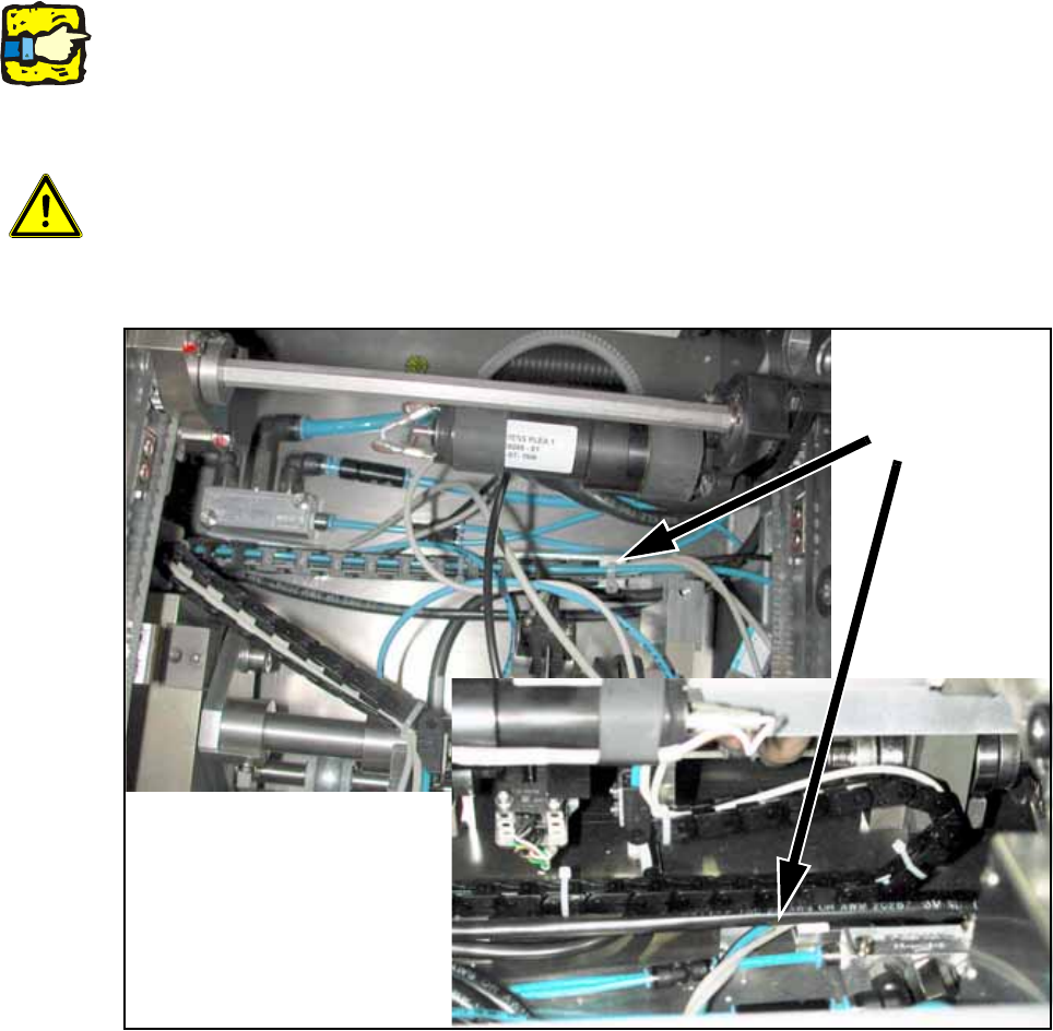
O Install the trailing cable distance block for conveyor track 1 (high distance block) under the first
conveyor side.
This trailing cable must run on the distance block for conveyor track 2.
The two distance blocks should be offset from each other by about 100 mm as in placement
area 2.
13
Make sure that the trailing cable stands vertically to the stopper and does not collide with the belt
of the width adjustment. The stopper must subsequently move freely over the entire conveyor
width, and the trailing cables must not tilt to the side. 13
13
13
13
Caution, crash hazard:
It is essential to ensure that the trailing cable does not collide with the conveyor belt of the width
adjustment, or the width adjustment itself. 13
13
Fig. 144
Distance
blocks
trailing cable