NR_Mechanischer_Stopper.pdf - 第168页
Assembly Instructions PCB Stopper Sin gle Conveyor SIPLACE S-27HM / HS-60 / D4 / D3 / HF- / X-Series Edition 06/2007 168 O Af fix the guide strip to the holders with two cylinder head bolt s with hexagon socket head M5 x…
Assembly Instructions PCB Stopper Single Conveyor SIPLACE S-27HM / HS-60 / D4 / D3 / HF- / X-Series
Edition 06/2007
167
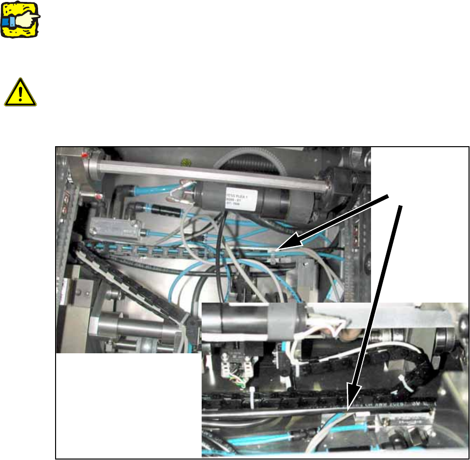
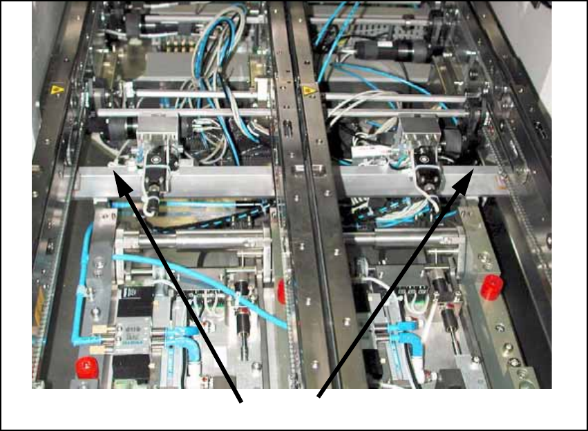
O Install the trailing cable distance block for conveyor track 1 (high distance block) under the first
conveyor side.
This trailing cable must run on the distance block for conveyor track 2.
The two distance blocks should be offset from each other by about 100 mm as in placement
area 2.
13
Make sure that the trailing cable stands vertically to the stopper and does not collide with the belt
of the width adjustment. The stopper must subsequently move freely over the entire conveyor
width, and the trailing cables must not tilt to the side. 13
13
13
13
Caution, crash hazard:
It is essential to ensure that the trailing cable does not collide with the conveyor belt of the width
adjustment, or the width adjustment itself. 13
13
Fig. 144
Distance
blocks
trailing cable
Assembly Instructions PCB Stopper Single Conveyor SIPLACE S-27HM / HS-60 / D4 / D3 / HF- / X-Series
Edition 06/2007
168
O Affix the guide strip to the holders with two cylinder head bolts with hexagon socket head
M5 x 20-DIN 912 (see Fig. 145).
Fig. 145 Attach guide strip
The distance block stuck on the floor of the mounting tub must be positioned so that the trailing
cables run parallel to the guide strip of the stopper. 13
Screws
Assembly Instructions PCB Stopper Single Conveyor SIPLACE S-27HM / HS-60 / D4 / D3 / HF- / X-Series
Edition 06/2007
169
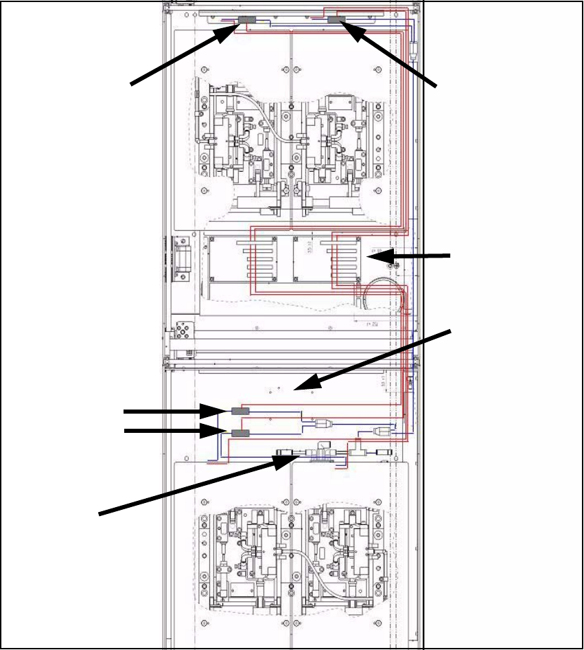
13.4 Cable and hose laying HS-60, D4
13.4.1 Complete overview
Fig. 146 Overview of pneumatic cabling (HS-60, D4)
Red lines: Power and data lines 13
Blue lines: Pneumatic power supply 13
Position of sole-
noid valves PA2
Position of sole-
noid valves PA1
Conveyor
conversion
board
Area of activity of
conveyor side trail-
ing cables
(allow space!)
Pneumatic
feed line
Position of sole-
noid valves PA2