NR_Mechanischer_Stopper.pdf - 第170页
Assembly Instructions PCB Stopper Sin gle Conveyor SIPLACE S-27HM / HS-60 / D4 / D3 / HF- / X-Series Edition 06/2007 170 13.4.2 Cable and hose laying P A1 O Label the cable s and pneumatic lines of the two stoppers to pr…
Assembly Instructions PCB Stopper Single Conveyor SIPLACE S-27HM / HS-60 / D4 / D3 / HF- / X-Series
Edition 06/2007
169
13.4 Cable and hose laying HS-60, D4
13.4.1 Complete overview
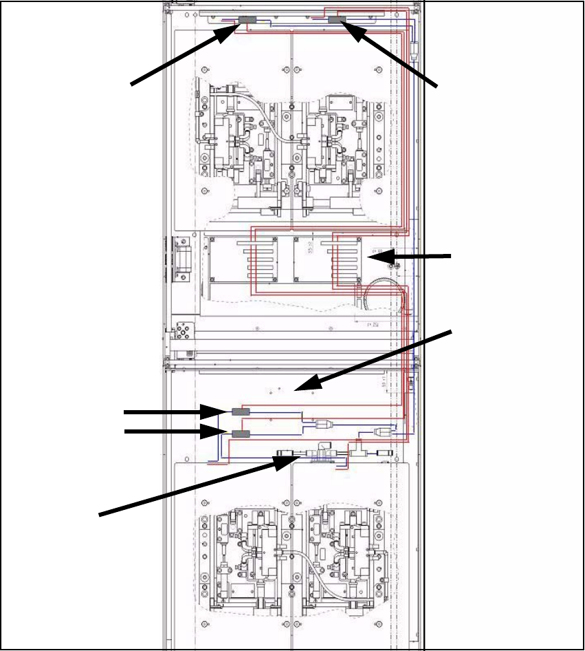
Fig. 146 Overview of pneumatic cabling (HS-60, D4)
Red lines: Power and data lines 13
Blue lines: Pneumatic power supply 13
Position of sole-
noid valves PA2
Position of sole-
noid valves PA1
Conveyor
conversion
board
Area of activity of
conveyor side trail-
ing cables
(allow space!)
Pneumatic
feed line
Position of sole-
noid valves PA2
Assembly Instructions PCB Stopper Single Conveyor SIPLACE S-27HM / HS-60 / D4 / D3 / HF- / X-Series
Edition 06/2007
170
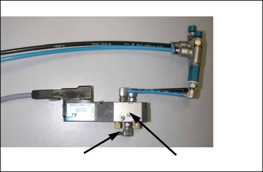
13.4.2 Cable and hose laying PA1
O Label the cables and pneumatic lines of the two stoppers to prevent any mix-ups.
O Connect both air pressure supply hoses (PUN 3) with both magnetic valves.
O Route the supply air hose of the valve for PA2 with the cables of the stopper of PA1 into PA2 .
O Bundle the cables and hoses with cable ties and fix the cables in position with self-adhesive
cable clamps.
O Plug the connectors of the connecting lines onto the conversion board according to the circuit
diagram (see Fig. 151, page - 175).
air pressure supply
magnetic valve
Assembly Instructions PCB Stopper Single Conveyor SIPLACE S-27HM / HS-60 / D4 / D3 / HF- / X-Series
Edition 06/2007
171
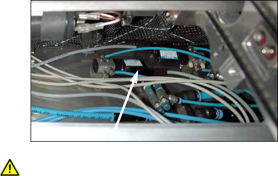
O Stick the valves onto the mounting tub with double-sided adhesive tape as shown in the fig-
ures.
Fig. 147 Valves
13
Make sure that the trailing cables of the conveyor sides are not impeded in their movement. 13
13
Valves