NR_Mechanischer_Stopper.pdf - 第183页
Assembly Instructions PCB Stopper Single Conveyor SIPLACE S-27HM / HS-60 / D4 / D 3 / HF- / X-Series Edition 06/2007 183 Fig. 157 Overview S-27HM (Fig . 4) Dual conveyor Legend (Figs. 3 and 4) Dual conveyor 14 14 1 Lifti…
Assembly Instructions PCB Stopper Single Conveyor SIPLACE S-27HM / HS-60 / D4 / D3 / HF- / X-Series
Edition 06/2007
182
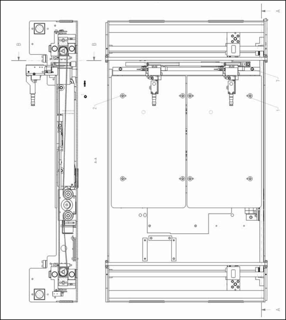
Fig. 156 Overview S-27HM (Fig. 3) Dual conveyor
Assembly Instructions PCB Stopper Single Conveyor SIPLACE S-27HM / HS-60 / D4 / D3 / HF- / X-Series
Edition 06/2007
183
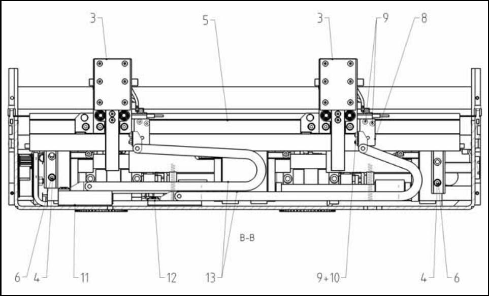
Fig. 157 Overview S-27HM (Fig. 4) Dual conveyor
Legend (Figs. 3 and 4) Dual conveyor 14
14
1 Lifting table plate Option Stopper DC
SP1
8 Energy chain holder
2 Lifting table plate Option Stopper DC
SP2
9 DIN EN ISO 7380-M3 x 6-A2
3 Basic unit Stopper S27 10 DIN 934 - M 3 - A2
4 Holder for guide strip S27 11 Distance block for energy chain,
compl.
5 Guide strip S27 12 Distance block for energy chain,
compl.
6 DIN912-M4 x 40-A2-70 13 Energy chain E04
7 DIN912-M5 x 20-A2-70
Assembly Instructions PCB Stopper Single Conveyor SIPLACE S-27HM / HS-60 / D4 / D3 / HF- / X-Series
Edition 06/2007
184
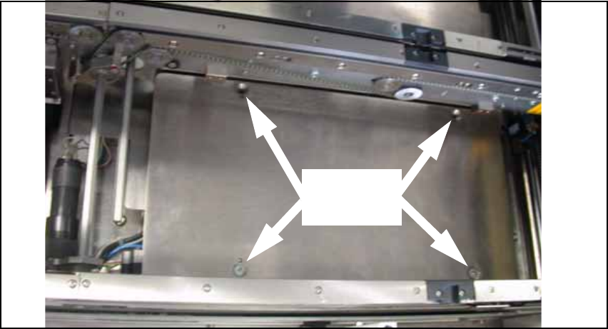
14.2 Installation
14.2.1 Installation of the guide rail with trailing cables
O Remove the lifting table plates.
Fig. 158 Lifting table plate with 4 screws (here conveyor track 1)
4 screws
per plate