NR_Mechanischer_Stopper.pdf - 第185页
Assembly Instructions PCB Stopper Single Conveyor SIPLACE S-27HM / HS-60 / D4 / D 3 / HF- / X-Series Edition 06/2007 185 O Place the wid th adjust ment in the center . T o do this, move the belt of the side adjustment by…
Assembly Instructions PCB Stopper Single Conveyor SIPLACE S-27HM / HS-60 / D4 / D3 / HF- / X-Series
Edition 06/2007
184
14.2 Installation
14.2.1 Installation of the guide rail with trailing cables
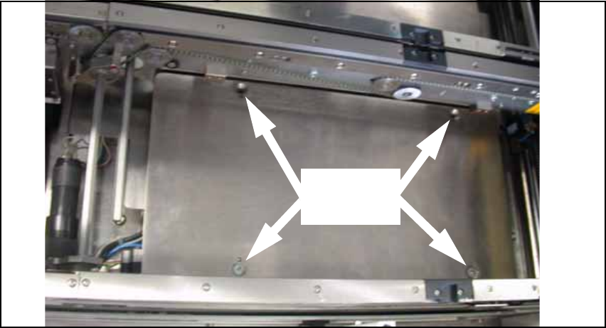
O Remove the lifting table plates.
Fig. 158 Lifting table plate with 4 screws (here conveyor track 1)
4 screws
per plate
Assembly Instructions PCB Stopper Single Conveyor SIPLACE S-27HM / HS-60 / D4 / D3 / HF- / X-Series
Edition 06/2007
185
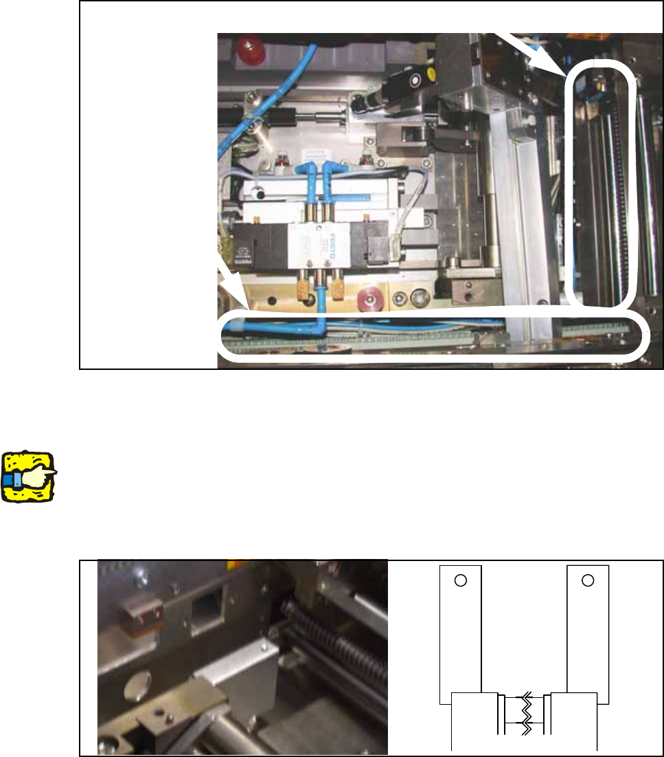
O Place the width adjustment in the center.
To do this, move the belt of the side adjustment by hand. This is located on the outside of con-
veyor track 1 of the lifting table.
Fig. 159 Belt of width adjustment
O Screw the guide rail holders to the lifting table on the left and right, each with two cylinder head
bolts with hexagon socket head M4 x 40 DIN 912.
Note:
The holders on the left and right are identical in shape but are installed at 180 degrees to each
other. Make sure when installing them that the projection of each holder lies on the external side
of the lifting table.
The length of the holders [03037444-xx] is 54 mm on the S-27HM.
Fig. 160 Holders on the lifting table
Belt of
width adjustment
Width adjustment
Holder
right
Con-
veyor
track 1
Holder
left
Con-
veyor
track 2
Lifting table
Assembly Instructions PCB Stopper Single Conveyor SIPLACE S-27HM / HS-60 / D4 / D3 / HF- / X-Series
Edition 06/2007
186
O Clean the conveyor tub in the area of the guide strip with a lint-free cloth moistened with ethyl
alcohol so that you have a clean sticking surface.
O To make cable laying easier later, bundle the hoses and cables of each stopper with a few ca-
ble ties.
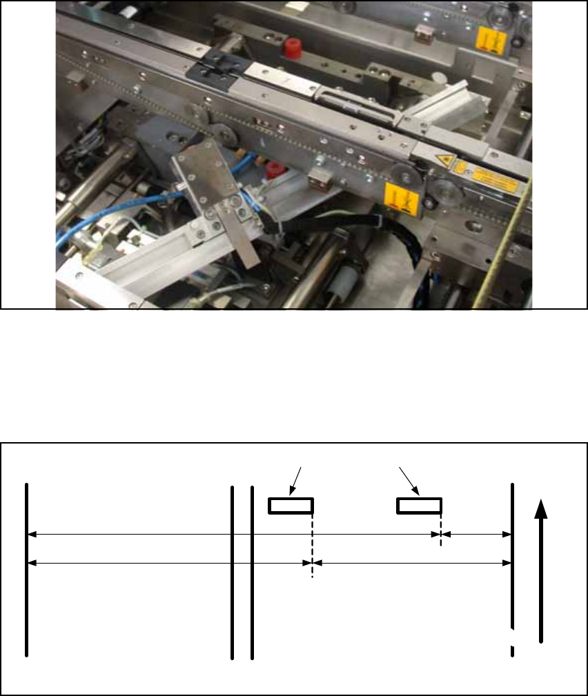
O Lay the guide rail in the lifting table diagonally.
Fig. 161 Guide rail with stopper in conveyor track 1
O Push the stopper with the high distance block onto the guide rail in conveyor track 1.
O Push the stopper with the low distance block onto the guide rail in conveyor track 2.
O Mark the following distances for the trailing cable distance blocks on the floor of the conveyor
mounting tub with a pen.
Fig. 162 Distances for the trailing cable distance blocks (S-27HM)
Conveyor track 2 Conveyor track 1
Distance block for energy chain
Left
conveyor side
Right
conveyor side
360 mm 150 mm
460 mm 50 mm
Transport direction